

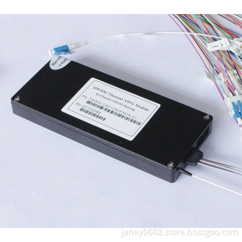
40CH 100G DWDM AWG Modules
- Min. Order:
- 1
- Min. Order:
- 1
Your message must be between 20 to 2000 characters
Contact Now| Place of Origin: | Guangdong,Shenzhen |
|---|---|
| Certificate: | ISO9001,ISO14001,RoHS |
96 Channel 50G Thermal AWG Mux/Demux Module
Optical Specification (Flattop AWG)
|
Parameters |
Condition |
Specs |
Units |
||
|
Min |
Typ |
Max |
|||
|
Number of Channels |
|
40 |
|
||
|
Number Channel Spacing |
100GHz |
100 |
GHz |
||
|
Cha. Center Wavelength |
ITU frequency. |
C -band |
nm |
||
|
Clear Channel Passband |
|
0.1 |
nm |
||
|
Wavelength Stability |
Maximum range of the wavelength error of all channels and temperatures in average polarization. |
0.05 |
nm |
||
|
-1 dB Channel Bandwidth |
Clear channel bandwidth defined by passband shape. For each channel |
0.4 |
|
|
nm |
|
-3 dB Channel Bandwidth |
Clear channel bandwidth defined by passband shape. For each channel |
0.6 |
|
|
nm |
|
Optical Insertion Loss at ITU grid |
Defined as the minimum transmission at ITU wavelength for all channels. For each channel, at all temperatures and polarizations. |
|
4.5 |
6.0 |
dB |
|
Adjacent Channel Isolation |
Insertion loss difference from the mean transmission at the ITU grid wavelength to the highest power, all polarizations, within the ITU band of the adjacent channels. |
25 |
|
|
dB |
|
Non-Adjacent, Channel Isolation |
Insertion loss difference from the mean transmission at the ITU grid wavelength to the highest power, all polarizations, within the ITU band of the nonadjacent channels. |
30 |
|
|
dB |
|
Total Channel Isolation |
Total cumulative insertion loss difference from the mean transmission at the ITU grid wavelength to the highest power, all polarizations, within the ITU band of all other channels, including adjacent channels. |
22 |
|
|
dB |
|
Insertion Loss Uniformity |
Maximum range of the insertion loss variation within ITU across all channels, polarizations and temperatures. |
|
1.0 |
1.5 |
dB |
|
Directivity(Mux Only) |
Ratio of reflected power out of any channel(other than channel n)to power in from the input channel n |
40 |
|
|
dB |
|
Insertion Loss Ripple |
Any maxima and any minima of optical loss across ITU band, excluding boundary points, for each channel at each port |
|
|
0.5 |
dB |
|
Optical Return loss |
Input & output ports |
40 |
|
|
dB |
|
PDL/Polarization Dependent Loss in Clear Channel Band |
Worst-case value measured in ITU band |
|
0.3 |
0.5 |
dB |
|
Polarization Mode Dispersion |
|
|
|
0.5 |
ps |
|
Maximum Optical Power |
|
|
|
23 |
dBm |
|
MUX/DEMUX input/ output Monitoring range |
|
-35 |
|
+23 |
dBm |
IL Represents the worst case over a +/-0.1nm window around the ITU wavelength
PDL was measured on average polarization over a +/- 0.1nm window around the ITU wavelength.
