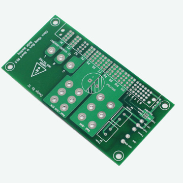
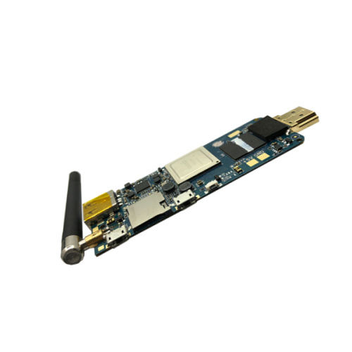
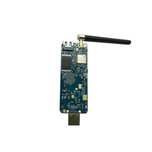

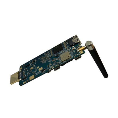
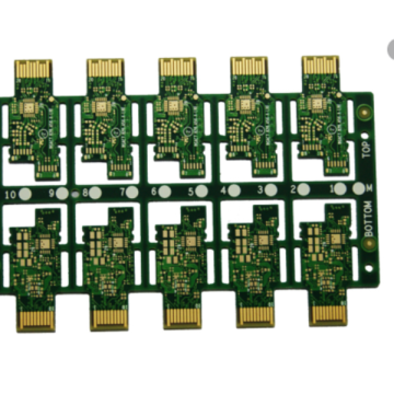
Ro4350B FR4 Hybrid PCB ain board assembly
-
$1.02≥1 Piece/Pieces
- Min. Order:
- 1 Piece/Pieces
- Min. Order:
- 1 Piece/Pieces
Your message must be between 20 to 2000 characters
Contact NowWhat is dielectric material in PCB?
1. Our commonly used PCB medium is Ro4350B FR4 hybrid Board material, and the relative dielectric constant of air is 4.2-4.7. This dielectric constant changes with temperature, and the maximum range of change can reach 20% in the temperature range of 0-70 degrees. The change of the dielectric constant will cause a 10% change in the line delay. The higher the temperature, the greater the delay. The dielectric constant also changes with the frequency of the signal, the higher the frequency, the smaller the dielectric constant. Below 100M, 4.5 can be used to calculate the inter-board capacitance and delay.
2. The transmission speed of the inner layer signal in the PCB of the general Ro4350B FR4 hybrid Board is 180ps/inch (1inch=1000mil=2.54cm). The surface layer generally depends on the situation, generally between 140 and 170.
3. High frequency board The actual capacitor can be simply equivalent to L, R, and C in series. The capacitor has a resonance point. At high frequencies (beyond this resonance point), it will appear inductive. The capacitance of the capacitor and the process are different, the resonance is The points are different, and the products produced by different manufacturers will also be very different. This resonance point mainly depends on the equivalent series inductance. Now, for example, the equivalent series inductance of a 100nF chip capacitor is about 0.5nH, and the ESR (equivalent series resistance) value is 0.1 ohms. Then the filtering effect is best at about 24M, and the AC impedance is 0.1 ohms. The equivalent inductance of a 1nF chip capacitor is also 0.5nH (the difference between different capacitance values is not too large), and the ESR is 0.01 ohms, which will have the best filtering effect around 200M. In order to achieve a better filtering effect, we use a combination of Electronic Resistor and Capacitor with different capacitance values. However, due to the effect of equivalent series inductance and capacitance, there will be a resonance point between 24M and 200M. There is a maximum impedance at the resonance point of the Characteristic impedance PCB, which is larger than the impedance of a single capacitor. This is an undesirable result. (In the section from 24M to 200M, small capacitors are capacitive, and large capacitors are already inductive. Two capacitors in parallel are equivalent to LC in parallel. The sum of the ESR values of the two capacitors is the series resistance of the LC loop. If LC is connected in parallel, If the series resistance is 0, then there will be an infinite impedance at the resonance point, which has the worst filtering effect. This series resistance will inhibit this parallel resonance phenomenon, thereby reducing the impedance of the LC resonator at the resonance point ). In order to reduce this effect, a capacitor with a larger ESR can be used as appropriate. ESR is equivalent to the series resistance in the resonant network, which can reduce the Q value, thereby making the frequency characteristics flatter. Increasing ESR will make the overall impedance converge. In the frequency bands below 24M and above 200M, the impedance will increase, while in the 24M and 200M frequency bands, the impedance will decrease. Therefore, the frequency of PCB switching noise must also be considered comprehensively.


Related Keywords