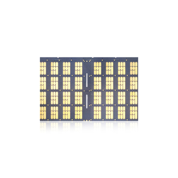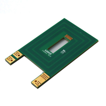


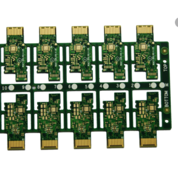
10 Layer FR-4 Multilayer BGA PCB
-
$8.30≥1 Piece/Pieces
- Min. Order:
- 1 Piece/Pieces
- Min. Order:
- 1 Piece/Pieces
Your message must be between 20 to 2000 characters
Contact Now
What is impedance control in PCB?
For analog or high-frequency digital circuits, it is essential to ensure the integrity of the signal propagating on the PCB. In fact, signals higher than 100 MHz will be affected by the impedance of the conductor traces, if not properly considered, it will lead to inconvenient errors, and it is particularly difficult to analyze. Fortunately, impedance control allows PCB designers and manufacturers to manage this phenomenon.
What is impedance?
Impedance measures the resistance when an alternating current flows through a circuit. It is a combination of capacitance and induction of high-frequency circuits. Like resistance, the unit of impedance is ohms. However, since resistance is a characteristic of direct current, do not confuse these two values. When a signal passes from a conductor with a certain impedance to another conductor with the same impedance, the signal will be transmitted in the best way. On the contrary, reflection and attenuation occur with different impedances, which leads to signal degradation.

Generally, the impedance of a track is between 25 and 125 ohms and depends on the following factors:
The width and thickness of the copper trace
Signal through via
The thickness of the core material or prepreg on both sides of the conductor track
Dielectric constant of core and prepreg
Distance from reference copper plane
With or without solder mask
Therefore, the circuit board designer must ensure that the impedance target value with a certain tolerance is achieved by selecting conductor traces and stacks when selecting high-frequency signals. The most advanced electronic CAD software will automatically perform these calculations.

Impedance control involves measuring the impedance of certain conductive paths in the circuit board manufacturing process and ensuring that it is within the limits communicated by the designer. This kind of technology is very expensive, but since the early 2000s, as the frequency of Electronic Components continues to increase, it has become a socially acceptable technology. For example, use it in the following products:
Analog and digital telecommunications
Video signal processing
Internet box, TV, GPS, video game, digital camera
Computer, tablet, mobile phone
Motor control module

When the signal must have a certain impedance to work normally, controlled impedance should be the first choice. In high frequency (High frequency board) applications, a constant impedance must be maintained on the entire circuit board to ensure the integrity of the transmitted data and the clarity of the signal. The longer the conductor path or the higher the frequency, the more adjustments need to be made. Lack of rigor at this level may increase the switching time of electronic equipment or circuits and cause unexpected errors.
After PCB assembly, it is difficult to analyze uncontrolled impedance. Depending on the lot, the components have different tolerance ranges. In addition, their characteristics are affected by temperature fluctuations, which may cause malfunctions. In this case, at first glance, replacing the components seems to be the solution, but in fact, the lack of impedance of the conductor trace is the problem.
Therefore, during PCB design, the impedance of the conductor trace and its tolerance must be checked in advance. The designer must work with the manufacturer to ensure that the component values meet the requirements.
Related Keywords