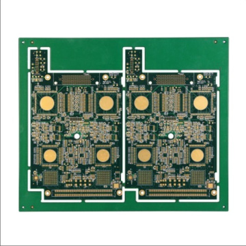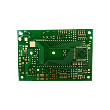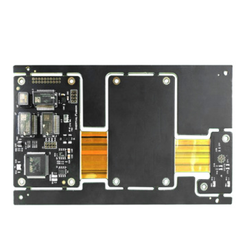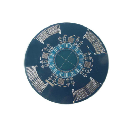
16 Layerm Hdi Pcb Assembly Pcba
-
$120.00≥1 Piece/Pieces
- Min. Order:
- 1 Piece/Pieces
- Min. Order:
- 1 Piece/Pieces
Your message must be between 20 to 2000 characters
Contact Now
What is HDI layout?
For HDI PCBs, apart from component and wiring density, almost nothing can distinguish these products from standard PCBs. I have seen designers point out that HDI boards refer to anything with 10 million or smaller vias, 6 million or smaller traces, or with 0.5 mm or smaller pin pitch. Your low cost 4 layer pcb supplier will tell you that HDI PCB uses blind holes about 8 mils or smaller, and the smaller blind holes are BVH PCBs drilled by laser.
In some respects, they are all correct, because there is no specific threshold for the composition of the HDI PCB layout. Everyone can agree that once the design includes microwells, it is an HDI board. In terms of design, you need to set certain design rules before you can touch the layout. Before establishing design rules, you should collect the capabilities of the manufacturer. After this is done, you need to set up design rules and some layout features
Trace width and via size. The width of a trace and its impedance and trace width will determine when you enter the HDI system. Once the trace width becomes small enough, the via will also become so small that it must be manufactured as a micro via.
Layer transition. The through hole needs to be carefully designed according to the aspect ratio, which also depends on the required layer thickness. Layer transitions should be defined early so that they can be placed quickly during the routing process.
gap. The traces must be separated from each other and kept separate from other objects (pads, components, planes, etc.) that are not part of the network. The goal here is to ensure compliance with HDI DFM rules and prevent excessive crosstalk.
Other trace restrictions, such as trace length adjustment, maximum trace length, and allowable impedance deviation during the trace process are also important, but they will apply to places other than HDI boards. Here, the two most important points are the via size and trace width. The gap can be determined in a variety of ways (for example, simulation) or following standard rules of thumb. Be careful with the latter, as this may result in excessive internal layer crosstalk or insufficient wiring density.




Related Keywords


