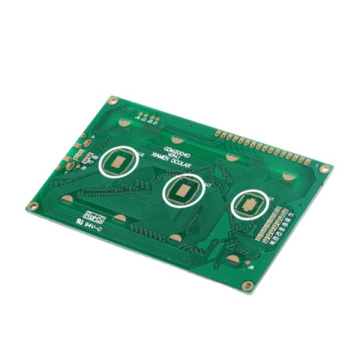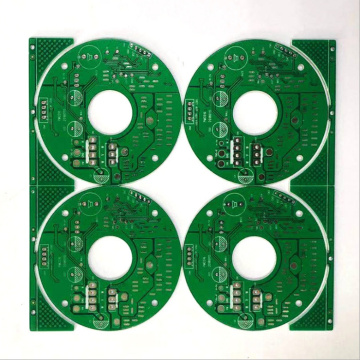

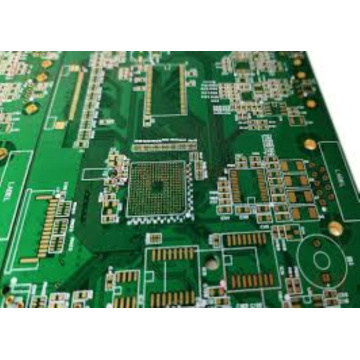
7days pcb 2L FR4 PCB low price ship
- Min. Order:
- 1 Piece/Pieces
- Min. Order:
- 1 Piece/Pieces
Your message must be between 20 to 2000 characters
Contact NowHow do you make a 4-layer PCB?
Four-layer PCB board drawing process:
1. Draw circuit schematics and generate network tables.
The process of drawing the schematic diagram involves the drawing of Electronic Components and the drawing of the package. It is basically not a problem to master these two kinds of drawing schematics. For the elimination of errors and warnings, general problems must be resolved. Complex schematics can be drawn using hierarchical schematics.
The shortcut keys used here: CTRL+G (set the net table spacing), CTRL+M (measure the distance between two points)
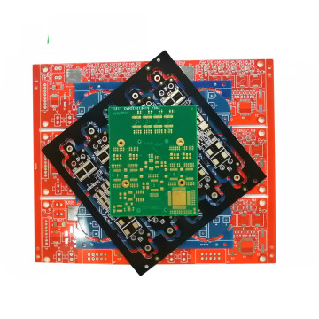
2. Planning the circuit board
How many layers do you want to draw? Should the electronic components be arranged on one side or on both sides? What is the size of the circuit board? and many more

The layout parameters and layer parameters are basically in accordance with the system default, and only a small number of parameters need to be set.

Note: If there is an error in the process of drawing the schematic diagram, but the PCB layout has been fixed, and you want to change the error without affecting the PCB layout, then this step is also performed, only in the last item of AddROOMS Do not check the Add before one item! Don't check it! Don't check it! The important thing is said three times. Otherwise it will re-layout, which is painful! !
The net list is the interface between the circuit schematic diagram editing software and the printed circuit board PCB design software. Only after the net list is loaded, can the circuit board be automatically routed.
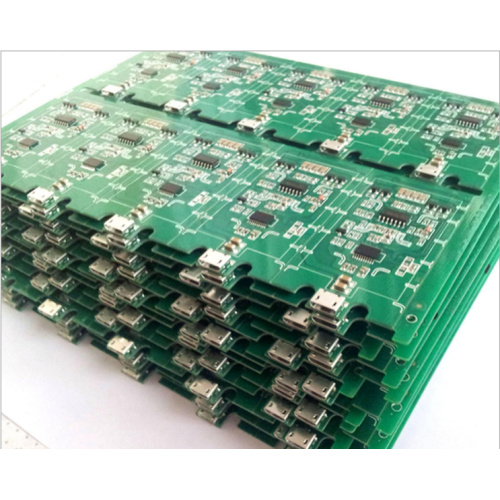
5. Layout of Electronic Components
In most cases, it is manual layout, or a combination of automatic and manual.
If you want to place Electronic Components on both sides: select the device and press the left button of the mouse, then press the L button; or click the component under the PCB interface and modify its attribute to bottomlayer.
Notice:
Electronic Components are arranged uniformly, so that the installation, plug-in, and welding operation texts are arranged on the current character layer, and the position is reasonable. Pay attention to the orientation to avoid being blocked, which is convenient for Electronic Components.
6. Wiring
Automatic wiring, manual wiring (the layout should be planned before wiring, matched with the internal electrical layer, and the internal electrical layer should be hidden for wiring. The internal electrical layer is usually a whole piece of copper film, and the pads with the same network name as the copper film When passing the internal electrical layer, the system will automatically connect it to the copper film. The connection form of the pad/via and the internal electrical layer, as well as the copper film and other pads that do not belong to the network, and the safety spacing can be included in the rules. set up.

Related Keywords