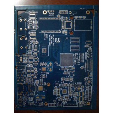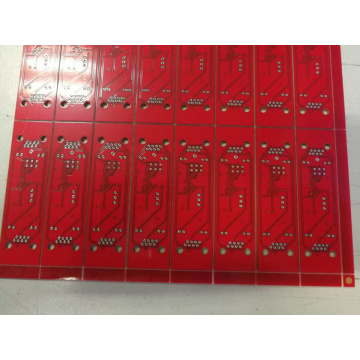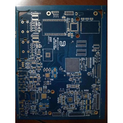
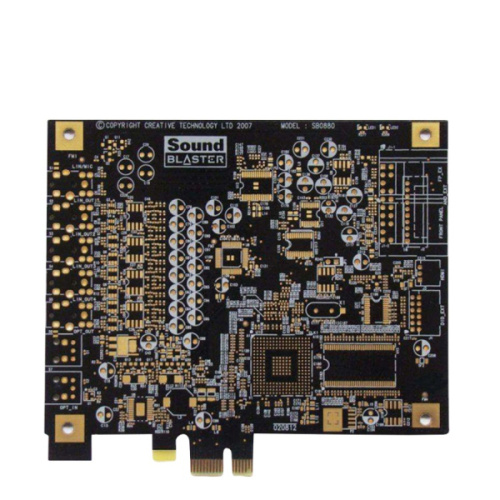
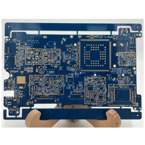
Low cost medical pcba pcb board
-
$0.52≥1 Piece/Pieces
- Min. Order:
- 1 Piece/Pieces
- Min. Order:
- 1 Piece/Pieces
Your message must be between 20 to 2000 characters
Contact NowWhat are pads and vias?
Pad and Via Design
The fixing of components on the printed board is realized by soldering the leads on the pads. The role of vias is to connect electrical connections at different levels.
(1) The size of the pad
The size of the pad is related to factors such as lead hole, minimum hole ring width and so on. The size of the pad should be maximized, but also consider the routing density. In order to ensure the reliability of the connection between the pad and the substrate, the lead hole is drilled in the center of the pad, and the hole diameter should be slightly larger than the diameter of the soldered component lead. The diameter of the component lead holes is preferably 0.5 mm, 0.8 ma△ and 1.2 mm. The width of the pad ring is selected within the range of 0.5 to 1.0 mm. Generally, the diameter of the pads for a dual in-line integrated circuit is 1.5 to 1.6 mm, and a printed wire with a width of 0.3 to 0.4 mm can be passed between adjacent pads. Generally, the ring width of the pad is not less than 0.3 mm, and the diameter of the pad is not less than 1.3 mm. Use the parameters recommended in Table 8-1 for the size of the actual pad.

(2) The shape of the pad
Choose pads of different shapes according to different requirements. Common pad shapes are round, square, oval, island and special, as shown in Figure 10.
How to distinguish between pads and vias_The difference between vias and pads
Circular pad: the outer diameter is generally 2 to 3 times the aperture, and the aperture is 0.2 to 0.3 mm larger than the lead.
Island-type pad: The connection between the pad and the pad is integrated, like an island on the water, so it is called an island-type pad. It is often used in the irregular arrangement of components, which is conducive to the dense fixing of components, and can greatly reduce the length and number of printed wires. Therefore, it is mostly used in high frequency circuits.
Other forms of pads are made by deforming the circular pads in order to make the printed wires pass between the adjacent pads. When using it, it should be used flexibly according to the actual situation.
(3) Selection of vias
The aperture should be as small as possible to less than 0.2 mm, which can improve the connection quality of the pads on both sides of the metallized via.
The difference between vias and through-hole pads in PCBs
In PCB design, both via VIA and pad PAD can achieve similar functions. They can be inserted into component pins, especially for devices in direct insertion (DIP) packages, which are almost the same.

1. The number of holes in the VIA is indicated in the design, and the number of holes is drilled. Then it has to go through process steps such as copper sinking, and the final actual aperture will probably be 0.1mm smaller than the designed aperture. For example, if the via hole is set to 0.5mm, the actual hole diameter is only 0.4mm.
2. The aperture of PAD will increase by 0.15mm when drilling. After the copper immersion process, the aperture is slightly larger than the designed aperture, about 0.05mm. For example, the design aperture is 0.5mm, the drilling will be 0.65mm, and the finished aperture will be 0.55mm.
3. VIA is covered with green oil in some default PCB processes, it may be blocked by green oil and cannot be soldered. Test points can't do it either.
4. The minimum width of VIA's welding ring is 0.15mm (under general process conditions) to ensure reliable copper immersion plating.
5. The minimum width of the pad's solder ring is 0.20mm (under the general process) to ensure the adhesion of the pad.

Can the vias be punched on the pads in the PCB design?
When designing a PCB board, sometimes due to the limitation of the board area or the complexity of the wiring, it will be considered to punch the vias on the pads of the SMD components. It has always been divided into two opinions: support and opposition. But in general, according to the author's years of practical experience, I feel that the method of punching holes on the pads is likely to cause virtual soldering of the SMD components, and it should be used with caution as a last resort. The two viewpoints are briefly described as follows.
Support: Generally, the purpose of punching through holes on the pads is to enhance the overcurrent capability or heat dissipation, so the backside is mainly covered with copper to connect the power supply or ground, and SMD components are rarely placed, so as to prevent tin leakage during reflow soldering , you can add green oil to the back of the via, and the problem is solved. This is the way I have dealt with the power supply part of the server motherboard that I have contacted.
Objection: Generally, SMD components can use one of the reflow soldering process or the wave soldering process. Wave soldering requires that the pad density should not be too high. If the pads are too dense, it is easy to cause a short circuit with tin. The SMD IC pins are relatively dense. Reflow soldering is the preferred solution. And the insert file can only use the wave soldering method.
There are many introductions to wave soldering and reflow soldering on the Internet. Engineers engaged in PCB design, please understand these production processes before knowing how to design.
There is a Fanout rule in Protel, which prohibits punching vias on the pads. Traditional processes prohibit this because the solder will flow into the vias. There are two processes, micro-via and plug-hole, which allow vias to be placed on the pads, but are very expensive. Consult the PCB factory. It is best not to punch through holes on the PAD, which is easy to cause virtual soldering. After tidying up the layout, the position of a small via should still be found.
However, for SMD components, during reflow soldering, the solder will flow away through the vias. So use with caution.
Related Keywords