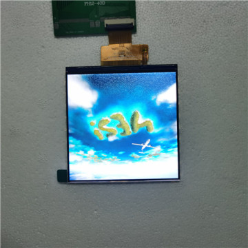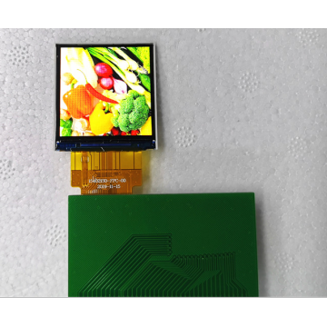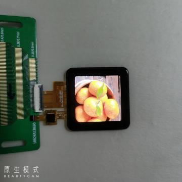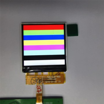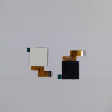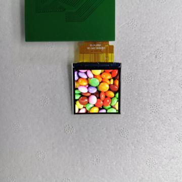

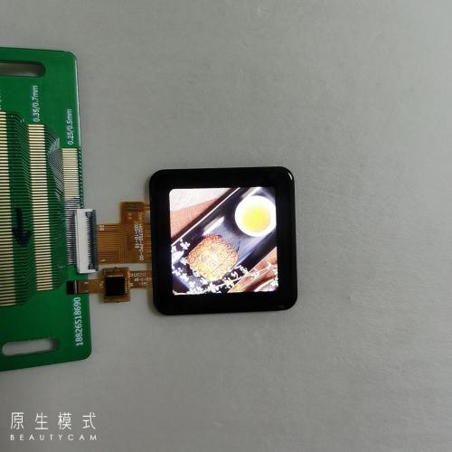
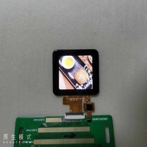
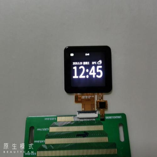
1.54 Inch TFT LCD Display
- Payment Type:
- T/T
Your message must be between 20 to 2000 characters
Contact Now| Payment Type: | T/T |
|---|
Liquid crystal refers to the intermediate status of a substance between solid (crystal) and liquid. When crystals with a high level of order in molecular sequence are melted, they generally turn liquid, which has fluidity but no such order at all. However, thin bar-shaped organic molecules, when they are melted, keep their order in a molecular direction although they lose it in molecular positions. In the state in which molecules are in a uniform direction, they also have refractive indices, dielectric constants and other physical characteristics similar to those of crystals, depending on their direction, even though they are liquid. This is why they are called liquid crystal. The diagram below shows the structure of 5CB (4-pentyl-4’-Cyanobiphenyl) as an example of liquid crystal molecules.


1. Introduction
1.1 Scope of application
This specification applies to the LCD module that is supplied by Tian Xian Wei
Technology CO., LTD.
LCD specification: Dots 240xRGBx240.
As to basic specification of the driver IC, refer to the IC (ST7789V2)
specification and data book.
All material & processing of the LCD module should be Lead Free.
1.2 TFT features:
Structure: TFT PANNEL+IC +FPC+BL+CTP;
IPS Type LCD
240dot-segment and 240 dot-common outputs;
65K Color can be selected by software;
White LED back light;
8bit MCU interface
1.3 Applications:
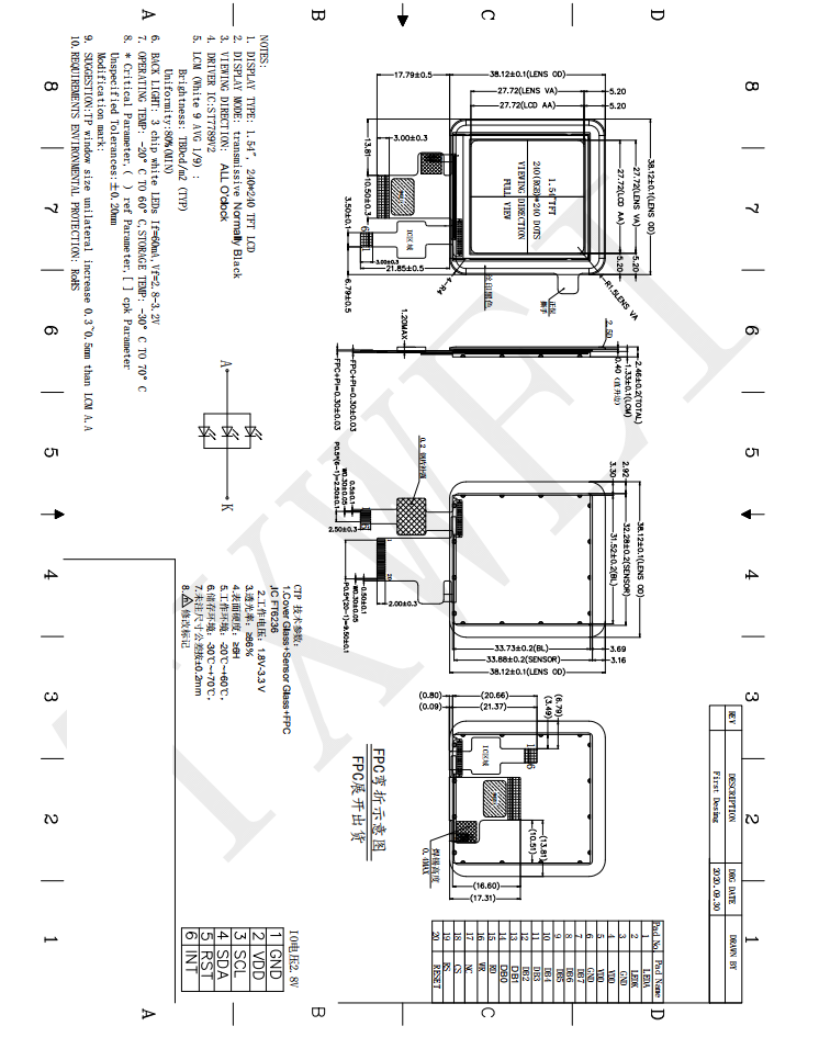
2. LCM General specification
|
ITEM |
Sandard value |
Unit |
|
LCD Type |
Normally Black |
-- |
|
Drive element |
TFT active matrix |
-- |
|
Number of pixels |
240*3RGB(H)X240(V) |
Dots |
|
Pixel arrangement |
RGB stripe |
-- |
|
Pixel Pitch (W*H) |
0.1155(W) × 0.1155(H) |
mm |
|
Active area |
27.72(W) ×27.72 (H) |
mm |
|
Viewing direction |
ALL O’CLOCK |
- |
|
TFT Driver IC |
ST7789V2 |
|
|
TFT interface |
8bit MCU interface |
- |
|
Approx. Weight |
TBD |
g |
|
LCM Size(W*H*T) |
31.52(W) ×33.72(H) ×1.33(T) |
mm |
|
LCM+CTP Size(W*H*T) |
38.12(W) ×38.12(H) ×2.46T) |
mm |
|
Touch structure |
G+G |
|
|
Touch Driver IC |
FT6236 |
- |
|
Touch Interface |
I2C |
|
3.Absolute Maximum Rating
|
Characteristics |
Symbol |
Min. |
Max. |
Unit |
|
LCM Operating Temperature |
TOPR |
-20 |
+60 |
°C |
|
LCM Storage Temperature |
TSTG |
-30 |
+70 |
°C |
|
TP Operating Temperature & Humidity(20% ~ 90%RH) |
TOPR |
-20 |
+60 |
°C |
|
TP SStorage Temperature & Humidity(20% ~ 90%RH) |
TSTG |
-30 |
+70 |
°C |
|
Humidity |
RH |
- |
90 |
% |
4.Electrical Characteristics
4.1 TFT DC Characteristics
|
Characteristics |
Symbol |
Min. |
Typ. |
Max. |
Unit |
|
Supply Voltage for I/O |
VDDIO |
-- |
-- |
-- |
V |
|
Supply Voltage for(DC/DC) |
VDD |
2.5 |
2.8 |
3.6 |
V |
|
Supply Voltage for(DC/DC) |
AVDD |
|
|
|
V |
|
Supply Voltage for(DC/DC) |
AVEE |
|
|
|
V |
4.2 Back-Light Unit Characeristics
The back-light system is an edge-lighting type with 3 white LEDs. The characteristics of the back-light are shown in the following tables.
|
Characteristics |
Symbol |
Min. |
Type |
Max. |
Unit |
Notes |
|
Forward Voltage |
VF |
2.8 |
-- |
3.2 |
V |
- |
|
Forward current |
IF |
-- |
60 |
- |
mA |
- |
|
Luminance(With LCD) |
Lv |
|
TBD |
-- |
cd/m2 |
- |
|
LED life time |
N/A |
---- |
30,000 |
-- |
Hr |
Note 1 |
Note:
(1) The “LED life time” is defined as the module brightness decrease to 50% of original brightness at IL=20mA/LED. The LED life time could be decreased if operating IL is larger than 25mA/LED.
Backlight circuit diagram shown in below:
5. Module Function Description
|
Pin No. |
Symbol |
LCM Description |
|
1 |
LEDA |
BACKLIGHT + |
|
2 |
LEDK |
BACKLIGHT- |
|
3 |
GND |
System Ground |
|
4 |
VDD |
POWER SUPPLY 2.4V ~ 3.3V |
|
5 |
VDD |
POWER SUPPLY 2.4V ~ 3.3V |
|
6 |
GND |
System Ground |
|
7-14 |
DB7-DB0 |
MCU parallel interface data bus |
|
15 |
RD |
Read enable in 8080 MCU parallel interface. |
|
16 |
WR |
Write enable in MCU parallel interface |
|
17 |
NC |
NC |
|
18 |
CS |
Chip selection pin |
|
19 |
RS |
Display data/command selection pin |
|
20 |
RESET |
Hardware reset |
|
Pin No. |
Symbol |
CTP Description |
|
1 |
GND |
System Ground |
|
2 |
CTP_VDD |
CTP_Power Supply (2.8V) |
|
3 |
CTP_SCL |
CTP_Clock Singnal (2.8V) |
|
4 |
CTP_SDA |
CTP_Data Singnal (2.8V) |
|
5 |
CTP_RST |
CTP _RESET PIN (2.8V) |
|
6 |
CTP_INT |
CTP_STOP Singnal (2.8V) |
6. Timing Characteristics
7.Optical Characteristics
8. Reliability Test Item
|
No. |
Test Item |
Test Condition |
Notes |
|
1 |
High Temp. Storage |
+70°C / 96H |
1. Functional test isOK. Missing Segment,short, unclear segment non-display,display abnormally and liquid crystal leakare un-allowed. 2. No low temperature bubbles,end seal loose andfall, frame rainbow.
|
|
2 |
Low Temp. Storage |
-30°C / 96H |
|
|
3 |
High Tempe. Operating |
+60°C / 96H |
|
|
4 |
Low Tempe. Operating |
-20°C / 96H |
|
|
5 |
High Temperature /Humidity storage |
50°C x 90%RH /96H |
|
|
6 |
Thermal and cold shock |
Static state, -20℃(30min) ~60℃ (30min),50 cycles |
9. Packing Method----TBD
- END -
Related Keywords
-
10.4 Inch TFT LCD Display
7.0 Inch TFT LCD Display
4.7 inch TFT LCD Module
Related ProductsProduct Categories-
TFT LCD(99)
- 0.96-2.0 Inch TFT LCD(2)
- 2.2 Inch TFT LCD(1)
- 0.96 Inch TFT LCD(1)
- 1.3 Inch TFT LCD(4)
- 1.14 Inch TFT LCD(1)
- 1.54 Inch TFT LCD(6)
- 1.77 Inch TFT LCD(2)
- 2.0 Inch TFT LCD(7)
- 2.1 Inch TFT LCD(2)
- 2.4 Inch TFT LCD(10)
- 2.6 Inch TFT LCD(1)
- 2.7 Inch TFT LCD(2)
- 2.8 Inch TFT LCD(8)
- 2.31 Inch TFT LCD(3)
- 3.0 Inch TFT LCD(8)
- 3.2 Inch TFT LCD(4)
- 3.5 Inch TFT LCD(12)
- 4.0 Inch TFT LCD(3)
- 4.3 Inch TFT LCD(2)
- 4.5 Inch TFT LCD(2)
- 4.7 Inch TFT LCD(2)
- 5.0 Inch TFT LCD(3)
- 5.5 Inch TFT LCD(2)
- 6.0 Inch TFT LCD(2)
- 6.86 Inch TFT LCD(1)
- 7.84 Inch TFT LCD(1)
- 7.0 Inch TFT LCD(2)
- 8.0 Inch TFT LCD(1)
- 9.35 Inch TFT LCD(1)
- 10.1 Inch TFT LCD(2)
- 10.4 Inch TFT LCD(1)
-
Portable Air Conditioner(1)