
Miniature Stepper Motor | Mini Step Motor
Your message must be between 20 to 2000 characters
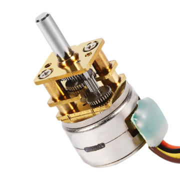
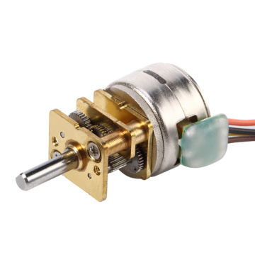
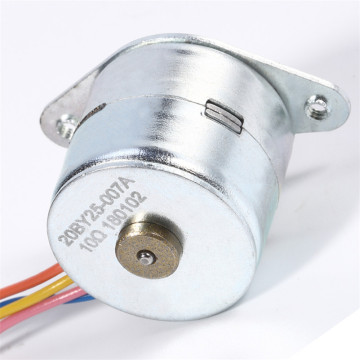
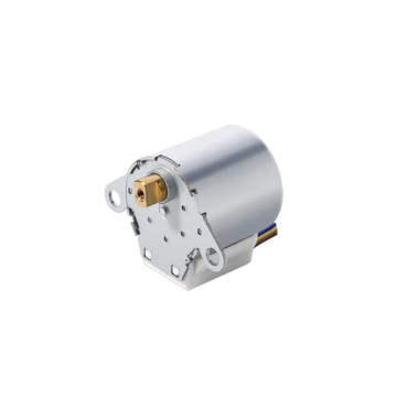
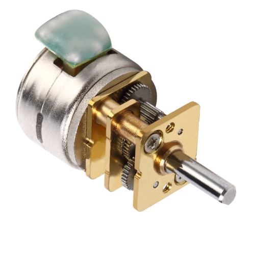
Contact Now15BYJ25-004 Reduction Stepper Motor Parameters
| MODEL | ITEMS | SPEC |
| 15BYJ25-004 |
Rated Voltage |
5V DC |
Phase |
2 |
|
Reduction Ratio |
1/52 |
|
Steo Angle |
0.35° |
|
Exciting Method |
2-2 |
|
Direct-current Resistance |
50Ω±10% |
|
No-load pull-in Frequency |
≥800Hz |
|
No-load pull-out Frequency |
≥1000Hz |
|
pull-in Torque |
≥80mN.m |
|
Insulation Class |
F |
Drawing of 15BYJ25-004 Reduction Stepper Motor

Applications of Stepper Motor
• 3D printing equipment
• Barrier gate
• Printing presses
• Automatic toilet seat cover
• Electric tailgate
• Nano sprayer
• Vending machines
• Aircraft – In the aircraft industry, stepper motors are used in aircraft instrumentations, antenna and sensing applications, and equipment scanning
• Automotive – The automotive industry implements stepper motors for applications concerning cruise control, sensing devices, and cameras. The military also utilizes stepper motors in their application of positioning antennas
• Chemical – The chemical industry makes use of stepper motors for mixing and sampling of materials. They also utilize stepper motor controllers with single and multi-axis stepper motors for equipment testing
• Consumer Electronics and Office Equipment – In the consumer electronics industry, stepper motors are widely used in digital cameras for focus and zoom functionality features. In office equipment, stepper motors are implemented in PC-based scanning equipment, data storage drives, optical disk drive driving mechanisms, printers, and scanners
• Gaming – In the gaming industry, stepper motors are widely used in applications like slot and lottery machines, wheel spinners, and even card shufflers
• Industrial – In the industrial industry, stepper motors are used in automotive gauges, machine tooling with single and multi-axis stepper motor controllers, and retrofit kits which make use of stepper motor controllers as well. Stepper motors can also be found in CNC machine control
• Medical – In the medical industry, stepper motors are utilized in medical scanners, microscopic or nanoscopic motion control of automated devices, dispensing pumps, and chromatograph auto-injectors. Stepper motors are also found inside digital dental photography (X-RAY), fluid pumps, respirators, and blood analysis machinery, centrifuge
• Scientific Instruments –Scientific equipment implement stepper motors in the positioning of an observatory telescope, spectrographs, and centrifuge
• Surveillance Systems – Stepper motors are used in camera surveillance
【Industry Encyclopedia】
Precautions for using PLC

1. Work environment
The PLC requires an ambient temperature of 0~55℃. It should not be placed under components with large heat generation during installation. The surrounding ventilation and heat dissipation space should be large enough. There should be a space of more than 30mm between the basic unit and the expansion unit; Ventilated shutters prevent direct sunlight; if the surrounding environment exceeds 55°C, an electric fan must be installed for forced ventilation.
Humidity In order to ensure the insulation performance of the PLC, the relative humidity of the air should be less than 85% (no condensation).
Vibration should keep the PLC away from strong vibration sources and prevent frequent or continuous vibration with a vibration frequency of 10 to 55 Hz. When vibration is unavoidable in the use environment, shock-absorbing measures must be taken, such as the use of shock-absorbing glue.
Power supply PLC power supply is 50Hz, 220(1±10%)V alternating current. The PLC itself has sufficient resistance to interference from the power line. For occasions with high reliability requirements or environments with particularly severe power interference, an isolation transformer with a shielding layer and a 1:1 transformation ratio can be installed to reduce the interference between the equipment and the ground. An LC filter circuit can also be connected in series at the power input end. FX series PLC has DC 24V output terminal, which can provide DC 24V power for input sensor (such as photoelectric switch or proximity switch). When an external DC power supply is used at the input, a DC stabilized power supply should be used. Because the ordinary rectifier and filter power supply, due to the influence of ripple, it is easy to make PLC receive wrong information.
2. External safety circuit
Emergency stop circuit. For dangerous loads that can cause harm to the user, in addition to considering it in the control program, an external emergency stop circuit should also be designed so that when the PLC fails, the power source of the load that causes the injury can be reliably cut off.
protect the circuit. Reversible operation control systems such as forward and reverse operation should be equipped with external electrical interlock protection; reciprocating operation and lifting movement control systems should be equipped with external limit protection circuits.
The programmable controller has self-checking functions such as a watchdog timer. When an abnormality is detected, all outputs are turned off. But when the programmable controller CPU fails, the output cannot be controlled. Therefore, for dangerous loads that can cause harm to the user, in order to ensure that the equipment runs in a safe state, it is necessary to design an external circuit for protection.
Protection against power overload. If the PLC power supply fails and the interruption time is less than 10 seconds, the PLC work will not be affected. If the power supply is interrupted for more than 10 seconds or the power drop exceeds the allowable value, the PLC will stop working and all output points will be disconnected at the same time; when the power supply is restored , If the RUN input is turned on, the operation is automatically performed. Therefore, necessary current-limiting protection circuits should be provided for some input devices that are prone to overload.
Alarm and protection of major failures. For places prone to major accidents, in order to ensure that the control system still provides reliable alarm and protection in the event of major accidents, signals related to major faults should be output through an external circuit so that the control system can operate in a safe condition.
3. Installation and wiring
Power cables, control cables, and PLC power cables and I/O cables should be wired separately, and the isolation transformer should be connected with PLC and I/O using double glue cables.
PLC should be far away from strong interference sources such as electric welders, high-power silicon rectifiers and large power equipment, and cannot be installed in the same switch cabinet with high-voltage electrical appliances.
The input and output of the PLC should be routed separately, and the switch quantity and analog quantity should also be laid separately. The transmission of analog signals should use shielded wires, the shielding layer should be grounded at one or both ends, and the grounding resistance should be less than 1/10 of the shielding layer resistance.
The connecting cables between the PLC basic unit and the expansion unit and functional modules should be laid separately to prevent interference from external signals.
Do not use the same cable for the AC output line and the DC output line. The output line should be as far away from the high-voltage line and power line as possible to avoid paralleling.
I/O terminal wiring
Input wiring
Generally, the input wiring should not exceed 30 meters. However, if the environmental interference is small and the voltage drop is not large, the input wiring can be appropriately longer. The input/output lines cannot use the same cable, and the input/output lines must be separated. Use normally open contacts to connect to the input terminal as much as possible, so that the compiled ladder diagram is consistent with the relay schematic diagram, which is easy to read.
Output connection
The output terminal wiring is divided into independent output and common output. In different groups, different types and voltage levels of output voltage can be used. But the output in the same group can only use the same type and the same voltage level power supply.
Since the output components of the PLC are packaged on the printed circuit board and connected to the terminal board, if the load connected to the output components is short-circuited, the printed circuit board will be burned. Therefore, a fuse is used to protect the output components.
When using a relay output, the size of the inductive load it bears will affect the service life of the relay. Therefore, when using an inductive load, the relay should have a long working life.
The output load of PLC may cause interference, so it is necessary to take measures to control it, such as DC output freewheeling tube protection, AC output resistance-capacitance absorption circuit, transistor and bidirectional thyristor output bypass resistance protection.
DC motor stepping motor DC motor 齿轮减速机 深圳网站建设 深圳seo优化 仿真恐龙制作 净水器代理 自贡净水器批发 厦门净水器 珠海净水器代理 天津净水器代理 重庆净水器代理 沈阳净水器代理 杭州净水器代理 汕头净水器代理 苏州净水器代理 温州净水器代理 宁波净水器代理 昆山净水器代理
Related Keywords
-
Brushless Motor Price | PMBLDC Motor | Brushless Permanent Magnet Motor
Fan Motor for AC Unit | Vent Fan Motor | Exhaust Blower Motor
24V Brushed Motor, High Speed Brush Motor & Small Brushed Motor Customizable
Related ProductsProduct Categories-
Gear Motor(27)
-
Stepper Motor(57)
-
Brushless Motor(11)
-
Carbon Brush Motor(21)
-
Other Products(820)
- Boom Barrier(147)
- Boom Gate System(29)
- Auto Gate Motor(60)
- 24V DC Motor(16)
- Toy DC Motor(3)
- 3D Printed DC Motor(3)
- N20 Gear Motor(1)
- Blower Motors(39)
- Furnace Blower Motor(21)
- DC Gear Motor(79)
- 1 HP Motor(58)
- Step Motor(86)
- Micro Stepper Motor(29)
- Brushless DC Motor(30)
- Brushless DC Electric Motor(25)
- Brush Motor(10)
- Brushed DC Electric Motor(10)
- Washer Pump Motor(1)
- Air Conditioner Motor(25)
- Brushless Permanent Magnet Motor(22)
- High Torque Brushless Motor(3)
- Treadmill Motor(3)
- 4 Phase Stepper Motor(9)
- Bipolar Stepper Motor(5)
- PM Stepper Motor(37)
- Geared Stepper Motor(57)
- High Speed Motor(12)