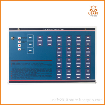

Ce Approved 10 Zones 2 Wire Conventional Fire Alarm Control Panel
-
USD100≥1 Piece/Pieces
- Payment Type:
- T/T
- Incoterm:
- EXW
- Min. Order:
- 1 Piece/Pieces
- Min. Order:
- 1 Piece/Pieces
- Delivery Time:
- 15 Days
Your message must be between 20 to 2000 characters
Contact Now| Place of Origin: | China |
|---|---|
| Productivity: | 1000pcs/month |
| Supply Ability: | 1000pcs/month |
| Payment Type: | T/T |
| Incoterm: | EXW |
| Certificate: | ISO9001,CE |
| HS Code: | 8531100000 |
Features
External (key-switch operated):
- Reset/resound/test zone lamps evacuate
- Silence alarm sounders
- Silence fault sounders
Internal:
- One man detector test
- Zone isolate
- Revert to short-circuit: fire (no resistors in call points)
External indicators:
- Sounder fault
- Battery/power supply fault
- Mains on
- Zone fire
- Zone fault
Internal indicators:
- Open circuit zone fault
- Short circuit zone fault
- Zone isolated
- Engineer test selected
Outputs:
- Two sounder circuits (alarm relay contacts can be obtained by connecting a relay to a sounder circuit)
Ancillary connections for expansion modules will allow the following:
- Repeater panels
- Multiple sounder outputs
- Connection to landlord panel
Specifications
|
|
2 (0.8A SUPPLY) |
4 / 6 (1.5A SUPPLY) |
8/10/12/14/16/18 (4.0A SUPPLY) |
|
POWER SPECIFICATION |
|||
|
MAINS SUPPLY VOLTAGE |
230V±10%Va.c.50/60Hz |
230V±10%Va.c.50/60Hz |
230V±10%Va.c.50/60Hz |
|
INTERNAL POWER SUPPLY |
27 Vd.c. |
27 Vd.c. |
27 Vd.c. |
|
TOTAL OUTPUT CURRENT LIMITED TO |
800mA@240VAC |
1500mA@240VAC |
4000mA@240VAC |
|
AUXILIARY POWER OUTPUT |
27 Vd.c. |
27 Vd.c. |
27 Vd.c. |
|
MAINS SUPPLY MONITORED FOR FAILURE |
YES |
YES |
YES |
|
BATTERY CHARGER MONITORED FOR FAILURE |
YES |
YES |
YES |
|
BATTERIES MONITORED FOR DISCONNECTION AND FAILURE |
YES |
YES |
YES |
|
DETECTOR CIRCUIT SPECIFICATION |
|||
|
NUMBER OF CIRCUITS |
2 |
4 or 6 |
8, 10, 12, 14,16,or 18 |
|
LINE FAULT MONITORED FOR OPEN CIRCUIT |
YES |
YES |
YES |
|
LINE FAULT MONITORED FOR SHORT CIRCUIT |
YES (Can be disabled) |
YES (Can be disabled) |
YES (Can be disabled) |
|
LINE FAULT MONITORED FOR DETECTOR REMOVAL |
Yes, if End of Line Monitor Unit fitted in place of End of Line Resistor |
||
|
END OF LINE RESISTOR (SUPPLIED) VALUE |
6800Ω,5% tolerance,0.25W |
6800Ω,5% tolerance,0.25W |
6800Ω,5% tolerance,0.25W |
|
DETECTOR CONTINUITY DIODES |
Silicon 1N4001 or Schottky type(required if End of Line Monitor Unit fitted to give Detector Removal Fault) |
||
|
CALL POINT RESISTOR VALUE (NOT SUPPLIED) |
470 to 680Ω, 0.5W |
470 to 680Ω, 0.5W |
470 to 680Ω, 0.5W |
|
MAXIMUM NUMBER OF SMOKE DETECTORS PER ZONE |
20(maximum detector current = 2mA) |
20(maximum detector current = 2mA) |
20(maximum detector current = 2mA) |
|
MAXIMUM NUMBER OF MANUAL CALL POINTS PER ZONE |
No limit |
No limit |
No limit |
|
SOUNDER CIRCUIT SPECIFICATION |
|||
|
NUMBER OF CIRCUITS |
2 |
2 |
2 |
|
END OF LINE RESISTOR VALUE |
6800Ω, 5%tolerance,0.25W |
6800Ω, 5%tolerance,0.25W |
6800Ω, 5%tolerance,0.25W |
|
LINE FAULT MONITORED FOR OPEN CIRCUIT |
YES |
YES |
YES |
|
LINE FAULT MONITORED FOR SHORT CIRCUIT |
YES |
YES |
YES |
|
OUTPUTS FUSED AT |
1 Amp |
1 Amp |
1.6 Amp |
|
MAXIMUM TOTAL OUTPUT CURRENT ALL OUTPUTS |
800mA |
1500mA |
4000mA |
|
MAXIMUM NO OF BELLS @ 25 mA EACH BELL |
32 |
56 |
120 |
|
MAXIMUM NO OF ELECTRONIC SOUNDERS @ 20 mA |
40 |
70 |
150 |
|
AUXILIARY RELAY CONTACTS (DO NOT CONNECT MAINS VOLTAGES) |
1A 30 Vd.c. max Voltage Free |
1A 31 Vd.c. max Voltage Free |
1A 32 Vd.c. max Voltage Free |
|
FUSES-ALL FUSES COMPLIANT TO IEC (EN60127 PT2) |
|||
|
MAINS TERMINAL BLOCK |
200mA T 20 mm |
400mA T 20mm |
630mA T 20mm |
|
SOUNDER OUTPUTS |
1A F 20mm |
1A F 20mm |
1.6A F 20mm |
|
AUXILIARY OUTPUT |
1A F 20mm |
1A F 20mm |
1A F 20mm |
|
BATTERY FUSE |
1.6A F 20mm |
1.6A F 20mm |
3A F 20mm |
|
DOOR RETAINING MAGNETS |
DO NOT USE PANEL POWER SUPPLY AS YOU WILL DRASTICALLY REDUCE BATTERY STAND-BY TIME |
||
|
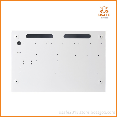
CONNECTION BLOCK |
|||
|
LARGEST ACCEPTABLE CONDUCTOR SIZE |
2.5mm2 |
2.5mm2 |
2.5mm2 |
|
SMALLEST ACCEPTABLE CONDUCTOR SIZE |
0.75mm2 |
0.75mm2 |
0.75mm2 |
|
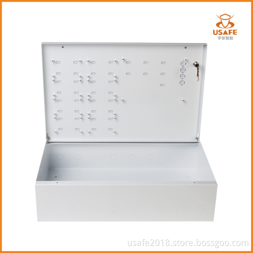
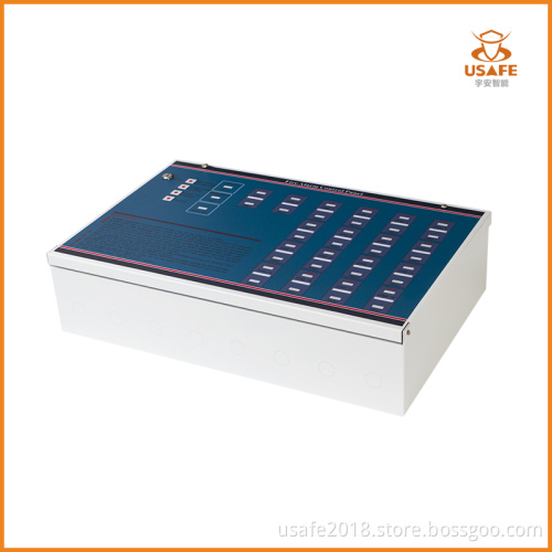
DIMENSIONS |
|||
|
ENCLOSURE(WIDTH x HEIGHT x DEPTH) |
415 x 265 x 100mm |
415 x 265 x 100mm |
415 x 265 x 100mm |
|
WEIGHT(WITHOUT BATTERIES) |
5100g |
5200g |
5500g |