12 Layer Buried Blind Via Rigid-flex PCB
- Payment Type:
- L/C, T/T, D/P, Paypal, Money Gram, Western Union
- Incoterm:
- FOB, CFR, CIF, EXW, FCA, CPT, CIP
- Min. Order:
- 1 Piece/Pieces
- Min. Order:
- 1 Piece/Pieces
- Transportation:
- Ocean, Air
Your message must be between 20 to 2000 characters
Contact Now| Place of Origin: | China |
|---|---|
| Productivity: | 10000 |
| Payment Type: | L/C,T/T,D/P,Paypal,Money Gram,Western Union |
| Incoterm: | FOB,CFR,CIF,EXW,FCA,CPT,CIP |
| Certificate: | ISO9001 |
| Transportation: | Ocean,Air |

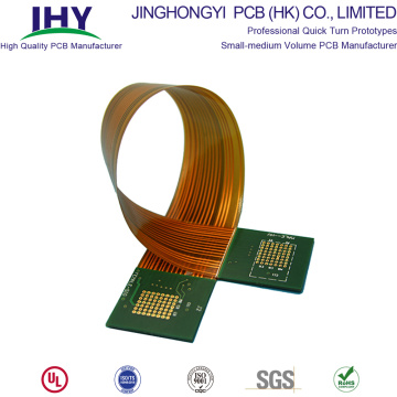
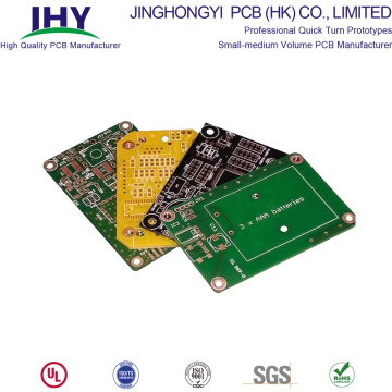
Type: 12 Layer Rigid-Flex PCB (Buried Blind Hole Plate)
Specification and size: 95mm * 151mm
Copper thickness: 18um
Board thickness: PCB = 1.0mm ± 0.1mm/FPC = 0.18mm ± 0.03mm
Aperture size: Through Hole 0.2mm, Blind Hole 0.1mm, Buried Hole 0.1mm
Surface treatment: Immersion Gold 2 Mil
Solder Mask: black ink, white character
Application field: Ship

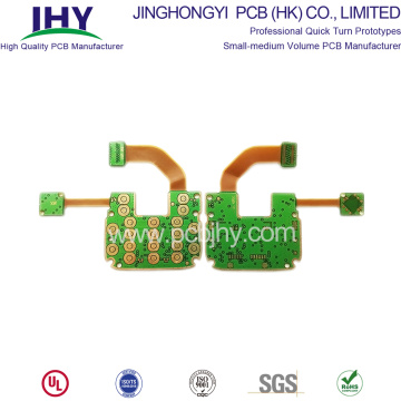
12 Layer Rigid-Flex PCB with 2 Layer Flex PCB
Model: Rigid-flex board-12 Layer
Layers: 12
Material: FR4+Polyimide
Surface treatment: HASL
Min. Line Width/ Spacing: 4/4 mil
Finish thickness: 0.2mm(flex), 1.6mm
Min Hot: 0.4mm
The design of a 12 layer rigid-flex PCB with 2 layer flex PCB is similar to that of the 10 layer rigid-flex with 2 layer flex PCB. However, the addition of 2 layers (i.e. the 11th and 12th layers) make the design a bit more complex than its 10 layer counterpart. The 2 layer flex PCB design of this circuit board makes it more flexible for manufacturing. Another benefit of this printed circuit board is that you can use exposed pads, and access holes on both the sides of the flex, and vias can be covered on either side. The 2 layer flex PCB consists of an insulating layer between the conductive layers. Plated through holes are used to create connections between the layers.
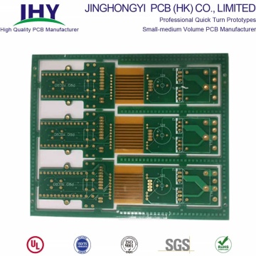
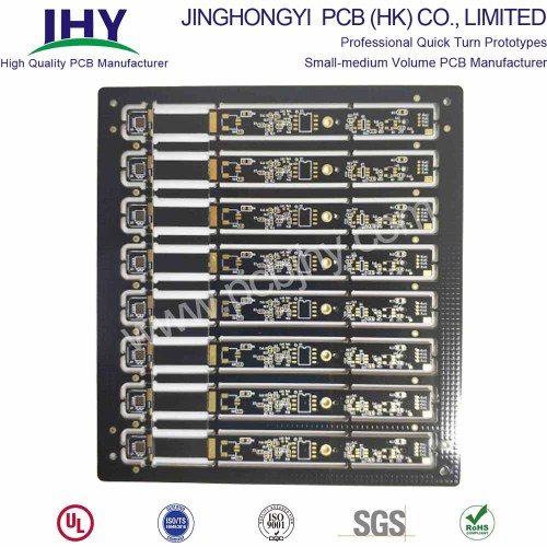
12 Layer Rigid-Flex PCB with Heat Sink
FPC Layer: 4 Layer Flexible circuits
We can manufacture these PCBs, with a board thickness of 0.5 mm ~ 3.0 mm. The copper thickness can vary from 0.5 OZ to 6 OZ. The finish thickness of the board is 0.2 mm (flex). We use FR4 and polyimide materials for these boards. For designing a custom PCB, you can choose from surface finish options, which include OSP, HASL, and immersion gold.

Rigid Board: 12 Layer
FPC Thickness: 0.3mm
FPC Raw Material: Polyimide
Rigid Board Material: FR4
Copper: 1OZ
FPC Surface Process: ENIG
FR4 Thickness: 1.6mm
Width/Space: 4mil/4mil
We have utilized a combination of FR4 and Polyimide materials. These materials support excellent thermal stability, mechanical properties, and electrical insulation. To ensure that heat distribution is also well achieved, we have added a heat sink component to the design of the PCB. Our fabrication capabilities allow us to provide PCBs with board thickness ranging from 0.02″ to 0.12″. Two layers are dedicated to power and ground. The power and ground planes allow for better distribution of electrical power. These features, along with high quality fabrication, makes the 12 layer PCB a perfect choice electrical and mechanical applications.

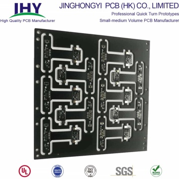
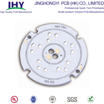
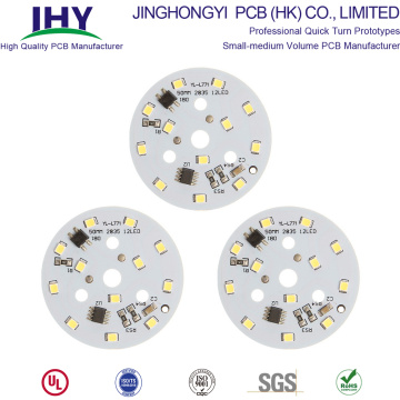
12-Layers-rigid-flex-PCB
Layers: 12 Layer
Thickness: 1.6mm
Out Layer Copper Thickness: 1 OZ
Inner Layer Copper Thickness: 1 OZ
Min hole size: 0.2mm
Min Line Width/Space: 3mil
Surface finish: ENIG
Features: High multilayer rigid-flex PCB structure
What is rational is actual and what is actual is rational - Georg Wilhelm Friedrich Hegel.
PCB is widely used in our household appliances, industrial production machinery and equipment. However, in general, PCB refers to rigid PCB. Although rigid PCB is the most widely used, but with different application scenarios and functional requirements, rigid-flexible Printed Circuit Board also emerged.
Rigid-flexible PCB has been widely used and developed, which is inseparable from its superior performance.
With the development of PCB design and production technology, there have been Double-sided rigid-flexible PCB, multi-layer rigid-flex PCB(3 Layer, 4 Layer, 5 Layer, 6 Layer, 8 Layer, 10 Layer, 12 Layer, 14 Layer), etc.
What's "Rigid-Flex PCB"?
Rigid-Flex circuit is made from a combination of a PI flex material sandwiched between FR4 epoxy or Polyimide rigid layers.
Rigid-Flex circuit boards are composed of a combination of rigid and flexible circuit boards that are permanently connected to one another.
Drilling and plating are processed throughout the sandwiched areas.
Flex-Rigid PCB is a good solution for dynamic application. The whole cost can be profitable and increase the reliability of the device.
Use of Rigid-Flex circuit boards can reduce the total cost of the final product.
Depending on the application, the complete Rigid-Flex circuit board may be manufactured either symmetrically with inward flexible layers, or asymmetrically with outward flexible layers

What makes Rigid-Flex Circuits different from Flex?
In a Rigid-Flex PCB, drilling and plating are processed through Rigid-Flex sandwiched areas.
In a flex PCB with rigid stiffener, no plating through rigid part.
Rigid-Flex is a complex assembly of Rigid parts and Flex parts. Rigid Part can be designed as a HDI product.
Multilayer Rigid-Flex Circuits Structure
Two or more conductive layers with either flexible or rigid insulation material as insulators between each one, outer layers may have covers or exposed pads.
Rigid-Flex has conductors on the rigid layers, which differentiates it from multilayers circuits with stiffeners. Plated through-holes extend through both rigid and flexible layers (with the exception of blind and buried vias).
Access holes or exposed pads without covers may be on either one or both sides; vias or interconnects can be fully covered for maximum insulation.
Stiffeners are optional.
Rigid-flexible PCB Instant Quote with fast delivery
Request quotes for Rigid-flexible printed circuit board prototypes
Rigid-flex printed circuit boards are PCB combining rigid and flexible board technologies.
A Rigid-flex PCB design improves the reliability of applications by reducing the amount of interconnect points. The less interconnection you have on a design, the stronger your circuit board is, ultimately lowering the final costs of your device or application.
JingHongYi PCB offers the best quality of single-sided, double-sided, or multi-layered Rigid-flex PCBs.
Why Rigid-flex PCB is widely used?
Due to the huge advantages of rigid-flexible PCB, it is widely used in the following products and industries:
- Space requirements can be minimized by applying 3D
- By removing the need for connectors and cables between the individual rigid parts the board size and overall system weight can be reduced.
- By maximizing space, there is often a lower count in parts.
- Less solder joints assure higher connection reliability.
- Handling during assembly is easier in comparison with flexible boards.
- Simplified PCB assembly processes.
- Integrated ZIF contacts provide simple modular interfaces to the system environment.
- Test conditions are simplified. A complete test prior to installation becomes possible.
- Logistical and assembly costs are significantly reduced with Rigid-Flex boards.
- It is possible to increase the complexity of mechanical designs, which also improves the degree of freedom for optimized housing solutions.
Rigid Flex PCB Design
Different applications determine the design idea of rigid-flexible PCB.
New product designs coupled with improved flex circuit technologies have introduced new design rules for rigid-flex PCBs.
When you design rigid-flex PCBs, think in terms of electromechanical factors that affect both the flex circuit and the rigid board.
Before we move onto the proper design of such a PCB, you must also keep certain factors in mind. Technology is always changing and evolving as the years go by; this means that people come up with new designs and methods of creating a Rigid Flex PCB are and will always be different, so there is no absolute way of making a rigid Flex PCB.
Moreover, depending on the application of the rigid flex and its purpose, the design and layout can be very different from the standard design, so keep in mind that the purpose of the PCB can significantly affect the design of the PCB.
The thickness of a Rigid Flex PCB is very subjective, as depending on the purpose of the build the difference can be minor or incredibly significant. The average board thickness for a rigid Flex PCB can be somewhere between 0.2mm and 0.4mm. 0.2mm is the average thickness of a single layer PCB circuit, and 0.4mm is the average thickness of a PCB with nearly 4 layers.

Only when many factors are considered comprehensively to create a Rigid Flex PCB that is both durable and flexible. All of these methods combine to make an effective and efficient circuit board.
Rigid Flex PCB's Technology and manufacturing Process
The technology that most manufacturers use on a PCB differs depending on the manufacturer, type of PCB, and the efficiency of the PCB. The efficiency of the PCB is one of the unique attributes about a rigid flex`s PCB, as depending on the task of the PCB the technology that a designer uses can differ significantly.

The stack up is the process of placing the layers for the rigid flex printed circuit board. Depending on the Rigid-flex circuit board the stack up can be of one, two, or four layer(s), and layers increase by the object`s application as well as its uses.
Related Keywords
-
Customized Single-sided 12V SMD LED PCB Circuit Board
HDI Fr4 Tg130 Tg150 Tg170 Tg180 Multilayer PCB
Shenzhen 10 Layer Gold Finger PCB Manufacturing
Related ProductsProduct Categories-
PCB Prototype(97)
-
Quick Turn PCB(33)
-
LED PCB(114)
-
Single Sided PCB(15)
-
Double Sided PCB(60)
-
Multilayer PCB(149)
-
Rigid PCB(22)
-
Flexible PCB(48)
-
Rigid Flex PCB(43)
-
Aluminum PCB(62)
-
Metal Core PCB(50)
-
Thick Copper PCB(106)
-
HDI PCB(61)
-
Impedance Control PCB(27)
-
BGA PCB(11)
-
High TG PCB(32)
-
Fr4 PCB(44)
-
Gold Fingers PCB(29)
-
PCB Application(5)
-
PCB Stencil(56)
-
PCB Assembly Service(67)
-
High Frequency PCB(47)