


IR Receiver Through-hole Optical Sensors Remote Receiver
- Payment Type:
- T/T, Paypal, Western Union
- Incoterm:
- FOB, EXW, FCA
- Min. Order:
- 5000 Piece/Pieces
- Min. Order:
- 5000 Piece/Pieces
- Delivery Time:
- 5-7 Business Days
- Transportation:
- Ocean, Land, Air
- Port:
- SHENZHEN
Your message must be between 20 to 2000 characters
Contact Now| Place of Origin: | China |
|---|---|
| Productivity: | 1000000000 pcs/week |
| Supply Ability: | 7000000000 pcs/week |
| Payment Type: | T/T,Paypal,Western Union |
| Incoterm: | FOB,EXW,FCA |
| Certificate: | GB/T19001-2008/ISO9001:2008 |
| HS Code: | 8541401000 |
| Transportation: | Ocean,Land,Air |
| Port: | SHENZHEN |
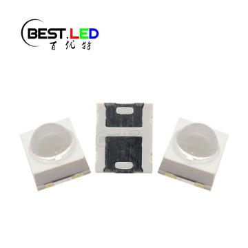
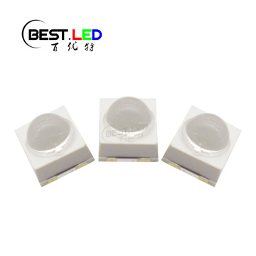
IR Receiver Through-hole Optical Sensors Remote Receiver
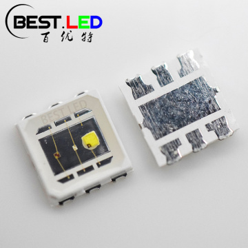
As we introduced before, there have two kind of IR receiver in total: SMD type and through-hole type.
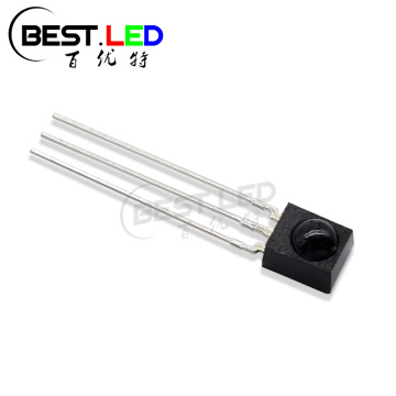
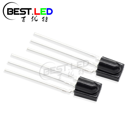
This BYT-0537KND was produce with a black lens, since this is a optical sensors, this black lens will be much better for their performance when they working. Becuase this product can received the signals, they can be widely used in IR system to control and operate devices, Security and pet gates ect. If you need some IR emitter and IR Receiver pair for your porject, just feel free to contact us for more detail about it~This BYT-0537KND can received the signal from IR LED such as: 940nm LED, 850nm LED or others.
Our quality won't let you disappointment!

Size of BYT-0537KND:

Electrical Optical Chararcteristics(Tc=25℃)
Vcc=5V
Vcc=3V
1.0
0.9
1.5
1.5
Vcc=5V
Vcc=3V
4.7
2.7
5.0
3.0
Paramete
Symbol
Condition
Min.
Typ.
Max.
Units
Supply Voltge Range
Vcc
2.7
5.5
V
Arrival Distance
L
L5IR=300mA
10
15
m
B.P.F Center Frequency
F0
38
KHZ
Reveiving angle
2θ1/2
70
deg
B.M.P Width
fBW
3.5
6
8.5
KHZ
Current Consumption
Icc
mA
Low Level Output Width
Vol
Isink=2.0mA
0.2
0.4
V
High Level Output Width
Voh
V
Peak Wavelength
λp
940
nm
Low Level Output Pulse Width
Tpwl
Vin=500u Vp-p
500
600
700
ns
High Level Output Pulse Width
Tpwh
Vin=50m Vp-p
500
600
700
ns
Are you still confused how this IR Receiver work? There are a simple picture as follow to explain how it can work:

Material of IR Receiver:
Same as some other thoruhg-hole LED or receiver. We also produce this product with high quality epoxy and pure gold wire;

Storage conditions
1. avoid continued exposure to the condensing moisture environment and keep the product away from rapid transitions in ambient temperature;
2. LEDs should be stored with temperature ≤30℃ and relative humidity<60%℃;
3. Product in the original sealed package is recommended to be assembled within 72 hours of opening;
4. Product in opened package for more than a week should be baked for 6-8 hours at 85-10℃;
LED MOUNTING METHOD
1, The lead pitch of the LED must match the pitch of the mounting holes on the PCB during component placement;
Lead-forming may be required to insure the lead pitch matches the hole pitch;
Refer to the figure below for proper lead forming procedures;
Do not route PCB trace in the contact area between the leadframe and the PCB to prevent short-circuits;

2. When soldering wires to the LED, each wire joint should be separately insulated with heat-shrink tube to prevent short-circuit contact.
Do not bundle both wires in one heat shrink tube to avoid pinching the LED leads;
Pinching stress on the led leads may damage the internal structures and cause failure;

3. Use stand-offs(Fig 3)or spacers(Fig 4)to securely position the LED above the PCB;
4. Maintain a minimum of 3mm clearance between the base of the LED lens and the first lead bend (Fig. 5. Fig. 6)
5.During lead forming, use tools or jigs to hold the leads securely so that the bending force will not be transmitted to the LED lens and its internal structures;
Do not perform lead forming once the component has been mounted onto the PCB;

Lead Forming Procedures
1. Lead Forming Procedures;
2. Do not bend the leads more than twice (Fig. 7);
3. During soldering, component covers and holders should leave clearance to avoid placing damaging stress on the LED during soldering(Fig 8);
4. The tip of the soldering iron should never touch the lens epoxy;
5. Through-hole LEDs are incompatible with reflow soldering;
6. If the LED will undergo multiple soldering passes or face other processes where the part may be subjected to intense heat please check with Best LED for compatibility;

Related Keywords
-
PC Type 2835 SMD 570nm LED Indication Yellow-green
High Bright 5mm Red DIP Oval LED Stopper
60-degree 2835 SMD LED Lens Series Blue Color
Related ProductsProduct Categories-
Custom LED(34)
-
Full Wavelength LED(469)
- 365nm LED(14)
- 400nm LED(24)
- 450nm LED(16)
- 470nm LED(16)
- 480nm LED(11)
- 495nm LED(12)
- 500nm LED(9)
- 520nm LED(18)
- 560nm LED(11)
- 590nm LED(22)
- 600nm LED(11)
- 617nm LED(11)
- 625nm LED(23)
- 635nm LED(13)
- 660nm LED(28)
- 680nm LED(9)
- 730nm LED(18)
- 760nm LED(12)
- 780nm LED(13)
- 810nm LED(23)
- 830nm LED(15)
- 850nm LED(37)
- 880nm LED(20)
- 940nm LED(36)
- 970nm LED(10)
- 1050nm LED(11)
- 1200nm LED(7)
- 1300nm LED(7)
- 1400nm LED(6)
- 1550nm LED(6)
-
IR LED(130)
-
IR Receiver(18)
-
SMD LED(243)
-
Domed LEDs(91)
-
LED Lamps(168)
-
RGB LED(62)
-
Flashing LED(26)
-
Red Smd Led(31)
-
Red Through-hole LED(42)
-
White SMD LED(98)
-
White Through-hole LED(50)
-
Blue SMD LED(35)
-
Blue Through-hole LED(48)
-
Green SMD LED(30)
-
Green Through-hole LED(49)
-
Yellow LED(53)
-
Orange LED(16)
-
Amber LED(20)
-
Pink LED(5)
-
UV LED(52)