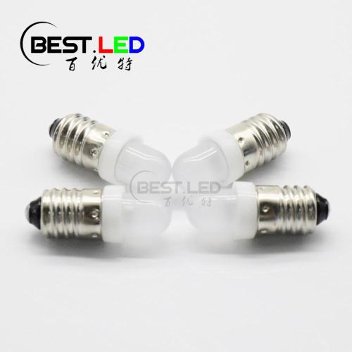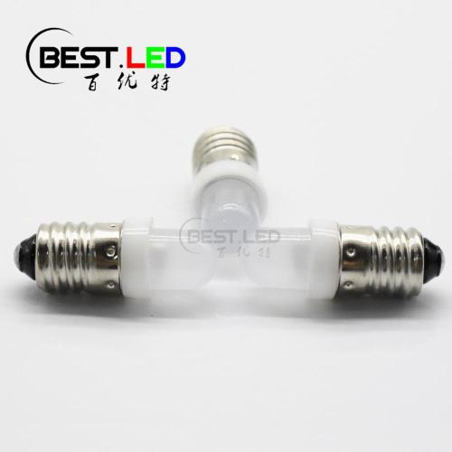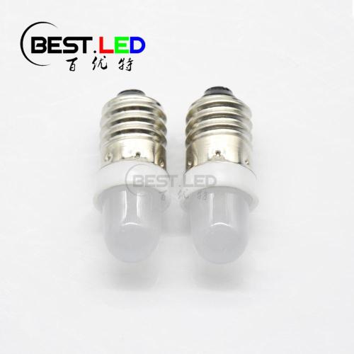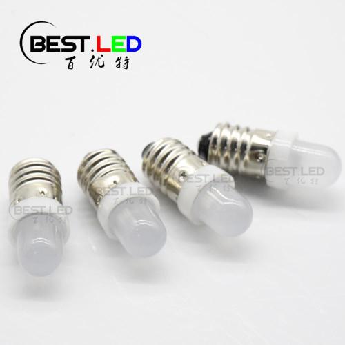
Flashing LED Mini Bulb 8mm RGB LED Fast
- Min. Order:
- 5000 Piece/Pieces
- Min. Order:
- 5000 Piece/Pieces
- Transportation:
- Ocean, Land, Air, Express
- Port:
- SHENZHEN
Your message must be between 20 to 2000 characters
Contact Now| Place of Origin: | China |
|---|---|
| Productivity: | 1000000 pcs/week |
| Supply Ability: | 1000000 pcs/week |
| Payment Type: | T/T,Paypal |
| Incoterm: | FOB,EXW,FCA |
| Certificate: | GB/T19001-2008/ISO9001:2008 |
| HS Code: | 8541401000 |
| Transportation: | Ocean,Land,Air,Express |
| Port: | SHENZHEN |
Flashing RGB LED Mini Bulb with Full Color:
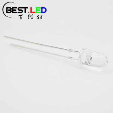
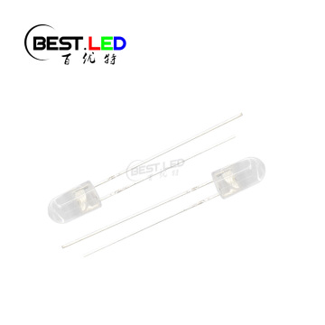
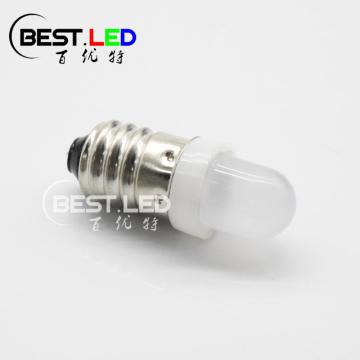
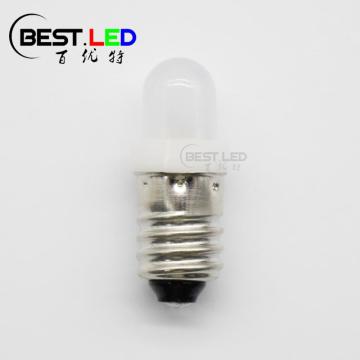
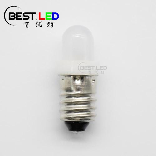
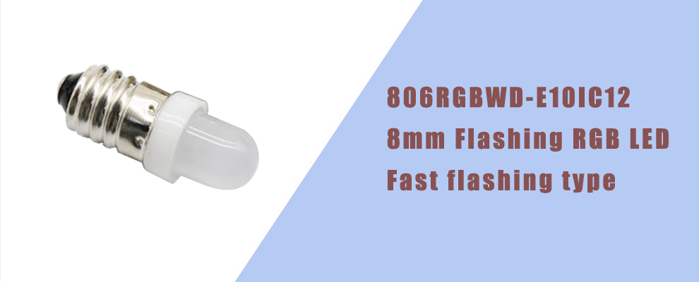
Same with those E10 mini bulb, this 806RGBWDE10IC12 do not have pins like common LED Lamps. It's Flashing LED that included all the color inside. Which is flashing RGB LED. With diffused milky lens, as long as you put this LED mini bulb into the circuit it will emits soft and colorful light for your project. In addition, this flashing LED got a faster frequency than 806RGBWDE10IC36.
If you need something flashing led for your projrt. Just feel free to contact us for more detail.
Flashing Mini LED Bulb RGB LED Size: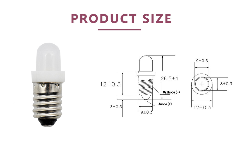
Flashing LED Features:
* Dimension of LED Lens: Flashing RGB LED;
* Fast flashing LED type;
* Lens type: Deep diffused Milky Lens;
* High reliability and high radiation intersity;
Electrical Parameters:
| Parameter | Symbol | Rating | Unit |
| Power Dissipation | Pd | 0.09 | W |
| DC Forward Voltage | VF | 4.5 | V |
| Operating Temperature |
Topr |
-25 ~ +80 |
℃ |
| Storage Temperature Range | Tstg | -40 ~ +80 |
℃ |
| Soldering Temperature | Tsol |
Reflowing soldering: 260℃ for 5 seconds Hand soldering: 300℃ for 3 seconds |
℃ |
| Electro-Static-Discharge(HBM) | ESD | 1000 | V |
| Service life under normal conditions | Time | 80000 | H |
|
Warranty |
Time | 2 | Years |
| Antistatic bag | Piece | 500 | Bag |
* Pulse forward current condition: Duty 1% and pulse width=10us.
* Soldering condition: Soldering condition must be completed with 3 secongds at 260℃
Electrucal Optical Characteristics(Tc=25℃)
| Parameter | Sysmblo | Min | Typ | max | Unit | Test Conditin |
| Contril Votage DC | VF |
|
3.5 | 4.5 | V | --------- |
| Luminous Intensity | IV | 400 | 8600 | 2500 | mcd |
DC=4.5V |
| Peak Wavelength |
λP |
|
625 465 525 |
|
nm |
DC=4.5V |
| Dominant Wavelength |
λD |
620 | 625 | 630 | nm |
DC=4.5V |
| Viewing Half Angle |
2θ1/2 |
|
40 |
|
deg | DC=4.5V |
| Flash Frequency | Fted | - | 12 | - | S | IDC=4.5V |
*Luminous Intensity is measured by ZWL600.
*θ1/2 is off-sxis angle at which the luminous intenity is half the axia luminous intensity;
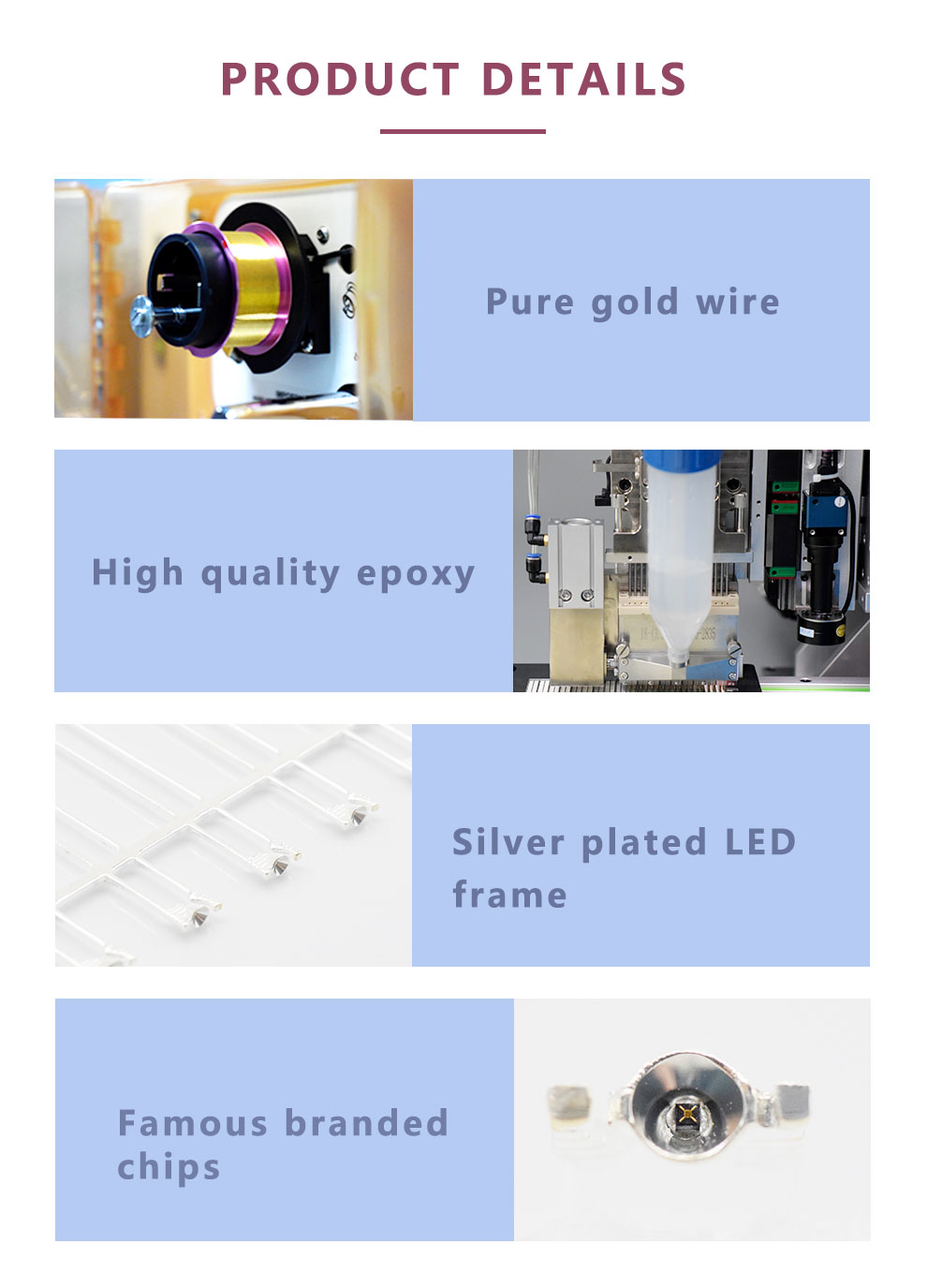
Material of Full Color LED Lamps:
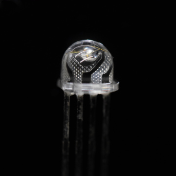
Manufacturing progress of through-hole LED:
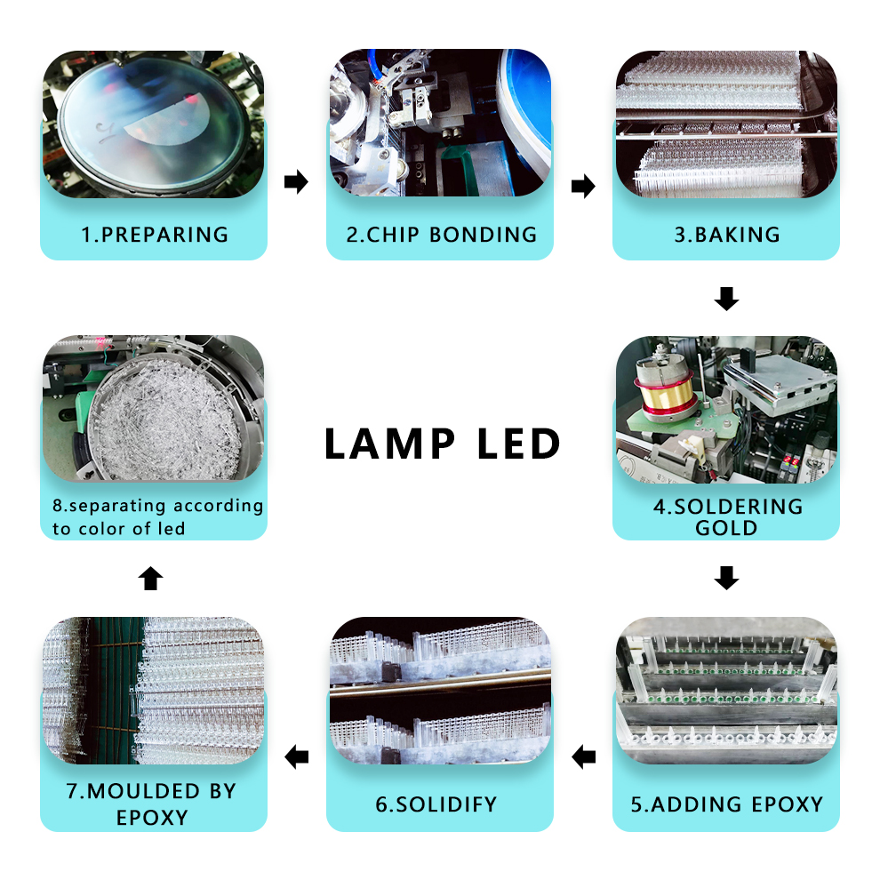
Compare with SMD LED, through-hole LED production will be more complicated. Which means it will take more production progress and production time:
First of all, we need to prepare the LED chip(this will be same as SMD LED production); Secondly, we will need to put the LED chip into the LED frame, and then we will need the pure gold wire to connect the cathode and anode of LED frame. There comes different, For SMD LED production, we need to put the epoxy to LED frame and wait until it dry by oven. However, for LED Lamps, we need to inject epoxy into the mold of lens and put all the things to oven for at least 8 hours until they dry. After that, we need to tae them from the oven and get the LED out of mold. And then we need to cut the pins of LED so that they can be easy to test.
Finally, we got the LED. In order to make sure the quality and the uniform as good as required. We also need to put all the LED to the separation machine and them we will got the LED with same bins.
Storage Conditions:
1. avoid continued exposure to the condensing moisture environment and keep the product away from rapid transitions in ambient temperature;
2. LEDs should be stored with temperature ≤30℃ and relative humidity<60%℃;
3. Product in the original sealed package is recommended to be assembled within 72 hours of opening;
4. Product in opened package for more than a week should be baked for 6-8 hours at 85-10℃;
LED MOUNTING METHOD
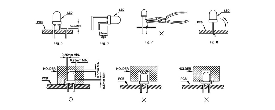
1, The lead pitch of the LED must match the pitch of the mounting holes on the PCB during component placement;
Lead-forming may be required to insure the lead pitch matches the hole pitch;
Refer to the figure below for proper lead forming procedures;
Do not route PCB trace in the contact area between the leadframe and the PCB to prevent short-circuits;

Noted:
○ Correct mounting method;
× Incorrect mounting method;
2. When soldering wires to the LED, each wire joint should be separately insulated with heat-shrink tube to prevent short-circuit contact.
Do not bundle both wires in one heat shrink tube to avoid pinching the LED leads;
Pinching stress on the led leads may damage the internal structures and cause failure;

Noted:
○ Correct mounting method;
× Incorrect mounting method;
3. Use stand-offs(Fig 3)or spacers(Fig 4)to securely position the LED above the PCB;
4. Maintain a minimum of 3mm clearance between the base of the LED lens and the first lead bend (Fig. 5. Fig. 6)
5. During lead forming, use tools or jigs to hold the leads securely so that the bending force will not be transmitted to the LED lens and its internal structures;
Do not perform lead forming once the component has been mounted onto the PCB;

Lead Forming Procedures
1. Lead Forming Procedures;
2. Do not bend the leads more than twice (Fig. 7);
3. During soldering, component covers and holders should leave clearance to avoid placing damaging stress on the LED during soldering(Fig 8);
4. The tip of the soldering iron should never touch the lens epoxy;
5. Through-hole LEDs are incompatible with reflow soldering;
6. If the LED will undergo multiple soldering passes or face other processes where the part may be subjected to intense heat please check with Best LED for compatibility;
Related Keywords


