


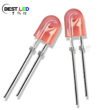
1400nm IR LED Far Red Infrared LED 3mm
- Min. Order:
- 50 Piece/Pieces
- Min. Order:
- 50 Piece/Pieces
- Transportation:
- Ocean, Land, Air
- Port:
- SHENZHEN
Your message must be between 20 to 2000 characters
Contact Now| Place of Origin: | China |
|---|---|
| Productivity: | 1000000000 pcs/week |
| Supply Ability: | 7000000000 pcs/week |
| Payment Type: | T/T,Paypal |
| Incoterm: | FOB,EXW,FCA |
| Certificate: | GB/T19001-2008/ISO9001:2008 |
| HS Code: | 8541401000 |
| Transportation: | Ocean,Land,Air |
| Port: | SHENZHEN |
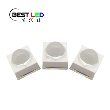
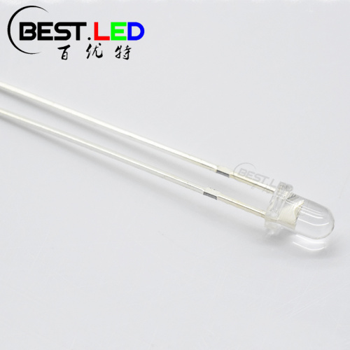
Small LED Lamps Size of Far Red IR LED;
This 3mm IR LED have a lens size of 3x5.3mm. Compare with other 3mm size of through-hole LED Lamps, this one got the strongest radiation. During the production, the frist step is welding the chip on the cup of LED frame and putting the glue into the mould strip. After that, insert LED frame between glue molding. In this progress, we will be able to adjust the viewing angle, the more we close to the top, the wider viewing angle we will get. In the same package size, the more viewing angle we get, the bigger radiation area we will get and the radiation distance will lost at the same time. We can adjust this as your required.

3mm Through-hole LED Lamps Product Size:

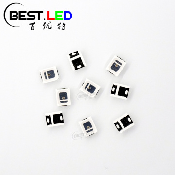
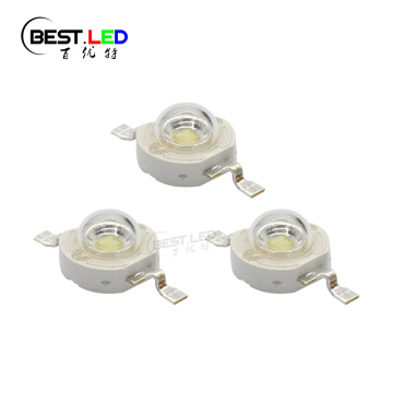
*This LED frame size are also available in UV LED, Yellow LED, Green LED, Blue LED and Red LED ect*
Storage conditions
1. avoid continued exposure to the condensing moisture environment and keep the product away from rapid transitions in ambient temperature;
2. LEDs should be stored with temperature ≤30℃ and relative humidity<60%℃;
3. Product in the original sealed package is recommended to be assembled within 72 hours of opening;
4. Product in opened package for more than a week should be baked for 6-8 hours at 85-10℃;
LED MOUNTING METHOD
1, The lead pitch of the LED must match the pitch of the mounting holes on the PCB during component placement;
Lead-forming may be required to insure the lead pitch matches the hole pitch;
Refer to the figure below for proper lead forming procedures;
Do not route PCB trace in the contact area between the lead frame and the PCB to prevent short-circuits;

2. When soldering wires to the LED, each wire joint should be separately insulated with heat-shrink tube to prevent short-circuit contact.
Do not bundle both wires in one heat shrink tube to avoid pinching the LED leads;
Pinching stress on the led leads may damage the internal structures and cause failure;

3. Use stand-offs(Fig 3)or spacers(Fig 4)to securely position the LED above the PCB;

4. Maintain a minimum of 3mm clearance between the base of the LED lens and the first lead bend (Fig. 5. Fig. 6)
5.During lead forming, use tools or jigs to hold the leads securely so that the bending force will not be transmitted to the LED lens and its internal structures;
Do not perform lead forming once the component has been mounted onto the PCB;
Lead Forming Procedures
1. Lead Forming Procedures;
2. Do not bend the leads more than twice (Fig. 7);
3. During soldering, component covers and holders should leave clearance to avoid placing damaging stress on the LED during soldering(Fig 8);

4. The tip of the soldering iron should never touch the lens epoxy;
5. Through-hole LEDs are incompatible with reflow soldering;
6. If the LED will undergo multiple soldering passes or face other processes where the part may be subjected to intense heat please check with Best LED for compatibility;

Related Keywords
-
Z-Power 3W Blue LED 450nm High Power LED
PC Type 490nm 495nm Cyan SMD LED 2835
PC Type 2835 SMD 570nm LED Indication Yellow-green
Related ProductsProduct Categories-
Custom LED(34)
-
Full Wavelength LED(469)
- 365nm LED(14)
- 400nm LED(24)
- 450nm LED(16)
- 470nm LED(16)
- 480nm LED(11)
- 495nm LED(12)
- 500nm LED(9)
- 520nm LED(18)
- 560nm LED(11)
- 590nm LED(22)
- 600nm LED(11)
- 617nm LED(11)
- 625nm LED(23)
- 635nm LED(13)
- 660nm LED(28)
- 680nm LED(9)
- 730nm LED(18)
- 760nm LED(12)
- 780nm LED(13)
- 810nm LED(23)
- 830nm LED(15)
- 850nm LED(37)
- 880nm LED(20)
- 940nm LED(36)
- 970nm LED(10)
- 1050nm LED(11)
- 1200nm LED(7)
- 1300nm LED(7)
- 1400nm LED(6)
- 1550nm LED(6)
-
IR LED(130)
-
IR Receiver(18)
-
SMD LED(243)
-
Domed LEDs(91)
-
LED Lamps(168)
-
RGB LED(62)
-
Flashing LED(26)
-
Red Smd Led(31)
-
Red Through-hole LED(42)
-
White SMD LED(98)
-
White Through-hole LED(50)
-
Blue SMD LED(35)
-
Blue Through-hole LED(48)
-
Green SMD LED(30)
-
Green Through-hole LED(49)
-
Yellow LED(53)
-
Orange LED(16)
-
Amber LED(20)
-
Pink LED(5)
-
UV LED(52)