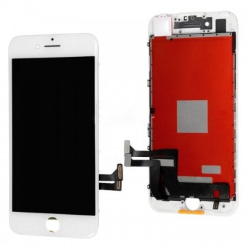
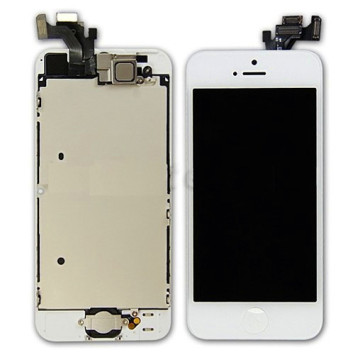
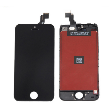
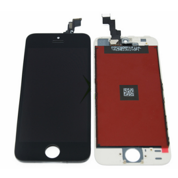
Home Button Flex for iPhone 5C Parts
- Payment Type:
- T/T, Paypal, Western Union
- Incoterm:
- FOB
- Min. Order:
- 1 Piece/Pieces
- Min. Order:
- 1 Piece/Pieces
- Delivery Time:
- 6 Days
- Transportation:
- Air
Your message must be between 20 to 2000 characters
Contact Now| Payment Type: | T/T,Paypal,Western Union |
|---|---|
| Incoterm: | FOB |
| Transportation: | Air |
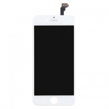
This is the backup spare parts for iPhone 5C Home Button Flex cable replacement.
Home button flex ribbon for iPhone 5C feature
- Home Button Flex ribbon replacement for iPhone 5C
- Weight: 15g
- Replacement parts
- Package include: 1X Home button key + 1X Home flex cable
- Compatible for iPhone 5C
How to replace Home Button flex on iPhone 5C
Step 1.
If your display glass is cracked, keep further breakage contained and prevent bodily harm during your repair by taping the glass.
Lay overlapping strips of clear packing tape over the iPhone's display until the whole face is covered.
Step 2.
Step 3.
Close the handle on the iSclack, opening the suction-cup jaws.
Step 4.
Hold onto your iPhone securely and close the handle of the iSclack to separate the suction cups, pulling the front panel up from the rear case.
Step 5.
- Press a suction cup onto the screen, just above the home button.
-
While holding the iPhone down with one hand, pull up on the suction cup to slightly separate the front panel assembly from the rear case.
-
Pull the plastic nub to release the vacuum seal on the suction cup.
-
Remove the suction cup from the display assembly.
-
Lift the home button end of the front panel up to gain access to the connectors near the top of the phone.
-
Open the display to about a 90º angle, and lean it against something to keep it propped up.
- Remove the two 1.6 mm Phillips #000 screws securing the metal battery connector bracket to the logic board.
Step 10.
- Remove the metal battery connector bracket from the iPhone.
Step 11.
- Use the flat edge of a spudger to pry the battery connector up off the logic board.
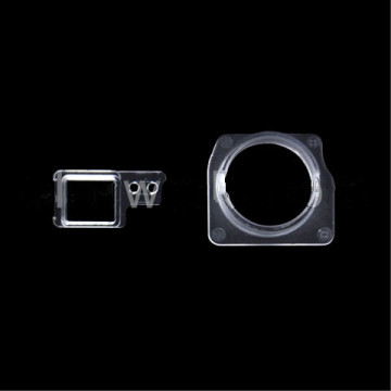
- Remove 4 Phillips #000 screws securing the front panel assembly cable bracket to the logic board: 2X 1.3mm screws, 1X 1.7mm screw, 1X 3.25mm screw
- Remove the front panel assembly cable bracket from the logic board.
Step 14.
- Use a plastic opening tool to disconnect the front-facing camera and sensor cable connector.
Step 15.
- Use a plastic opening tool to disconnect the LCD cable connector.
- Remove the front panel assembly from the rear case.
Step 17.
- Remove the two 1.3 mm Phillips #000 screws securing the home button bracket to the display assembly.
Step 18.
Use a plastic opening tool to pry the edge of the home button ribbon cable up from the display assembly.
Start under the contact points on the right and work to the left.
Step 19.
- Remove the home button ribbon cable from the display assembly.
Related Keywords