
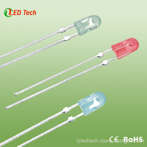
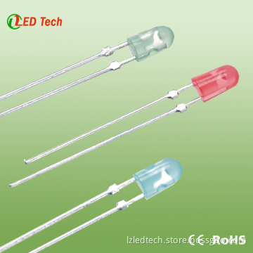
3mm 5mm 10mm led diode High CRI high lumen led diode components
- Delivery Time:
- 7 Days
Your message must be between 20 to 2000 characters
Contact Now| Place of Origin: | China (Mainland) |
|---|
| SPECIFICATIONS Revision: 1.0 (1) Absolute Maximum Rating | |||||||
| Parameter | Symbol | Absolute Maximum Rating | Unit | ||||
| Forward Current | IF | 20 | mA | ||||
| Peak Forward Current | IFP | 100 | mA | ||||
| Reverser Voltage | VR | 5 | V | ||||
| Power Dissipation | PD | 80 | mw | ||||
| Electrostatic Discharge | ESD | 1000 | V | ||||
| Operating Temperature | TOP | -25℃ 80℃ | ℃ | ||||
| Storage Temperature | TSTG | -5℃ 45℃ | ℃ | ||||
| Lead Storage Temperature | TSOL | Max.260℃ FOR 5 SECONDS MAX | |||||
| IMP Conditions:Pulse Width≤10mess and duty≤1/10 (2) Initial Electrical/Characteristics | |||||||
| Parameter | Symbol | Condition | Min | Avg | Max | Unit | |
| Forward Voltage | VF | IF=20mA | 2.8 | 3.0 | v | ||
| Reverse Current | IR | VR=5v | 10 | μA | |||
| Viewing Angle | θ/2 | IF=20mA | 50 | deg | |||
| Luminous Intensity | IV | 6000 | 8000 | mcd | |||
| Peak Wavelength | λp | nm | |||||
| CRI | Ra | 92 | 95 | Ra | |||
| Luminous Flux | Φ | 6.5 | 7.5 | Lm/w | |||
| Spectrum bound | X | 0.43 | 0.46 | ±0.015 | |||
| Y | 0.41 | 0.44 | ±0.015 | ||||
| Color lukewarm | K | 2800 | K | ||||
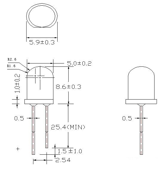
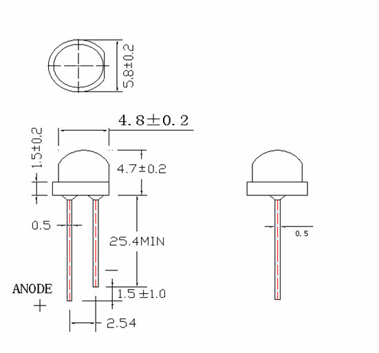
| 2.TYPICAL INITIAL OPICAL/ELECTRICAL CHARACTERISTICS Please refer to Figures:In page3 3.OUTLINE DIMENSIONS AND MATERIALS Please refer to drawing:In page2 Material as follows:Resin Epoxy Lead frame:Ag plating copper ally | |||||||
| Manufacturer: | LZ | Current: | 20mA | CRI: | >95 |
| Color temperature: | 2800k, 5600k, 7000k | Shape Type: | Round / straw hat | Leg: | long / short |
| Voltage: | 2.9 -3.0 / 3.0-3.1 / 3.1-3.2v | Lumen/w: | 110-120lm/w | Lumen: | 6.5-7.5lm |
| Colloid: | Clear | Power: | 0.06w | Light loss: | <0.1% / 1kh |
| Life: | 50,000h | Certificate: | RoHS, CE | Warranty: | 5years |
 Reliability Performance Page: 4 Revision: 1.0 Test items And Result
 | Test classification | Test item | Test Standard | Test Duration | Sample Size | C/E |
| Life test | Room temperature DC operating life test | Ta=25℃±5℃ IF=20mA | 1000 hrs | 20pcs | 0/1 |
| Environment Test | Thermal Shock Test | -10℃±5℃ 100℃±5℃ 5min. 10sec. 5min. | 50cydes | 20pcs | 0/1 |
| Temperature Cycle Test | -40℃±5℃ 85℃±5℃ 30min. 5sec. 30min. | 50cydes | 20pcs | 0/1 | |
| High Temperature & High humidity Test | Ta=85℃±5℃ RH=85%±0.5%RH | 1000 hrs | 20pcs | 0/1 | |
| High Temperature Storage | Ta=100℃±5℃ | 1000 hrs | 20pcs | 0/1 | |
| Low Temperature Storage | Ta=55℃±5℃ | 1000 hrs | 20pcs | 0/1 | |
| Mechanical Test | Resistance to Soldering Heat | Ta=230℃±5℃ | 5 sec | 20pcs | 0/1 |
| Lead Integrity | Load 2.5N(0.25kgf) 0° ~ 90°~ 0° | 3 times | 20pcs | 0/1 |
 Installation 1.Storage Under the storage conditions of 30℃ or less and humidity less than 60%RH, the LEDs can be storage for 3months. Storage in a sealed container with moisture absorbent material can prolong the storage time to a certain extent bad storage conditions may cause the lead frames to corrode or degradation of LED characteristics. It is recommended that the LEDs be used as soon as possible. 2. Static electricity Static electricity of surge voltage damages the LED .Damaged LED will show some unusual chrematistics such as the forward voltage becomes lower or the LED do not light at the low current even not light. All devices equipment and machinery must be properly grounded. At the same time, it is recommended that wrist Bands or anti-electrostatic gloves anti-electrostatic containers be used when dealing with the LED. 3. Design Consideration When designing a circuit, the current through each LED must not exceed the absolute maximum rating specified for each LED .In the meanwhile , resistors for protection should be applied otherwise slight voltage shift will cause big current change, bum out may happen. Thermal Design is paramount important in because heat generation may result in the Characteristics decline, such as brightness decreased, Color changed and so on. Please consider the heat generation of the LED when making the system design. 4. Lead Forming Any lead forming must be done before soldering, not during or after soldering. When forming leads ,the leads should bent at a point at least 3mm from the base of the expose bulb. Bending at the same point twice or even more should be avoided. Please use proper tools to hold and bent the leads, do not use the base of the lead frame as a fulcrum during lead forming .Bending s tress to the base of the lead frame may cause character is tics change on LED or even break it. Just for the same reason, when mounting the LED on to printed circuit board, the holes on the circuit board should be exactly aligned with the leads of the LED. 5. Soldering Be careful because damages always caused during soldering. Please note that stress to the leads and expose bulb should be avoided during soldering particularly when heated. When soldering, leave certain distance from soldering joint to base, the distance is determined by different soldering techniques.
 -

Manufacturer of led lighting,recessed slimline /wide led aluminum Profile for flex led strip lighting
-
Mounted on wall aluminum groove linear smd 5050 led strip light rgb
-
Top Quality linear luminaire Accessories
-
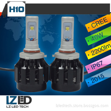
H10 LED Car Lights 12V Replacement Bulbs Super Bright LEDs 20Wx2 2200LM LED headlight bulbs
Related Keywords
-
Manufacturer of led lighting,recessed slimline /wide led aluminum Profile for flex led strip lighting
Mounted on wall aluminum groove linear smd 5050 led strip light rgb
Top Quality linear luminaire Accessories
H10 LED Car Lights 12V Replacement Bulbs Super Bright LEDs 20Wx2 2200LM LED headlight bulbs
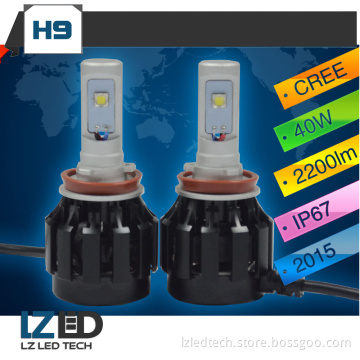
H9 All in one led auto lights 40W 2200LM Auto Front Bulb Automobiles Headlamp 6000K Car Lighting system
Related Products-
led diode prodaja srbija High CRI high lumen led diode components
-
red led diode 660nm High CRI high lumen led diode components
-
micro led diode High CRI high lumen led diode components
-
3mm 5mm 10mm led diode High CRI high lumen led diode components
-
5mm high brightness led diode High CRI Ra led diode components