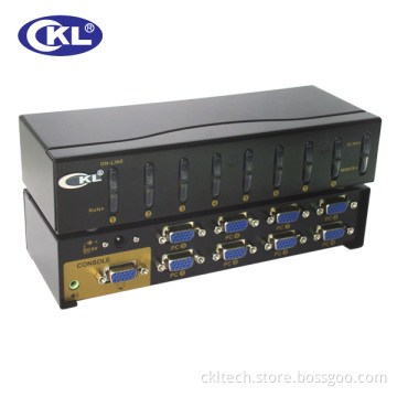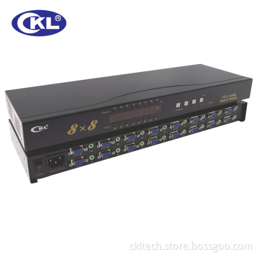
8*8 IR Remote Control VGA Matrix Switch
- Payment Type:
- L/C, T/T, D/P
Quantity:
Your message must be between 20 to 2000 characters
Contact NowBasic Info
Basic Info
| Place of Origin: | China(Mainland) |
|---|---|
| Payment Type: | L/C, T/T, D/P |
Product Description
Product Description
Panel interface description:
1. INPUT Indicator light (Orange) ---------- Detecting / indicating input devices (such as: Computer) is connected.
2. OUTPUT Indicator light (Orange) (Green) ------- Detecting / indicating input devices (such as: Computer) is connected.
3. LED Digital tubes (from left to right) -------. Represent the output port (1-2-3-4-5-6-7-8)
4. The Digital in the LED tube (Blue) ------- represent the input port.
5. POWER Indicator light (Orange) -------- Power indicator.
6. Button ( from left to right) ------Esc/Enter ( exit / enter key), - (reduce key), + (plus key), Set / (set/shift key).
7. IR------ Infrared receiver.
Panel key description:
1. Set / (set/shift key)
Power on, Press Set / key, get into" settings / shift" state. At the same time, to the left of the first LED digital tube flashing (a second light, a second off).
Press again Set / key, Second LED digital tube display digital started flashing. At the same time, the first digital display digital restoration of normal state. So, the operation is cycle until the eighth digital tube.
Please go to the second, the third step if you need to change your digital display digital.
2. + (plus key)
After the first step operation (Digital is in the twinkling state), press"+"key, it can modify the display digital. And every time press "+"key, Digital display digital automatic plus one(Digital 1---8 in between cycle).
3. - (reduce key)
After the first step operation (Digital in the twinkling state), Press"-"key, it can modify the display digital. And every time press "-"key, Digital display digital automatic reduce one. (Digital 1---8 in between cycle)
4. Esc/Enter (Exit / enter key)
After the operation of the first, the second and the third step(the corresponding input port number), Press Esc/Enter key, Digital display return to a normal state (Digital is not in the twinkling state). At the same time, ( According to the digital display digital)switch 8 video / audio input signal to corresponding to the 8 video / audio output device 8.
Note 1: 8 digital tube (from left to right) are respectively corresponding to the 8 video / audio output port (equipment)
Note 2: 8 digital tube display digital (from left to right) are respectively corresponding to the 8 video / audio input port (signal )
Remote control button description:
Button(2)----represent "Set/ " Button(4)--- represent -" + "
Button(6)---- represent "-" Button(8)---- represent "Esc/Enter"
Note: 1. Except for the button 2, 4, 6, 8, the remaining function button operation is invalid
2. Remote operating method is the same with functions of panel key.
Features description:
1.8 ways VGA signal + 8 AUDIO signal output.
2. LED lamp for the detection of each input / output device connection status.
3. LED digital tube display each path corresponds to the input port number.
4. Various scenes of storage and call, single channel or full channel browsing.
5. Power off protection.
6. High bandwidth matrix switching chip, image clarity and stability.
7.200ns Using high-speed switching circuit, the switching time 200ns.
8. Multiple control modes: The front panel buttons, infrared remote control.
9. Matrix design, arbitrary cross input output.
Related Keywords
Related Keywords